A step-by-step speed regulation method for self-adaptive diesel engine

A step-by-step speed regulation and diesel engine technology, applied in mechanical equipment, engine control, machine/engine, etc., can solve problems such as inconvenient, complicated and troublesome replacement work, and achieve prevention of human error, good control effect, and high speed small error effect

Active Publication Date: 2018-07-13
ZHUZHOU CSR TIMES ELECTRIC CO LTD
View PDF6 Cites 0 Cited by
  • Summary
  • Abstract
  • Description
  • Claims
  • Application Information

AI Technical Summary

Problems solved by technology

[0004] 1. Replace the governor spring, but the replacement work is more complicated, and due to technical reasons, it cannot be guaranteed that the problem can be solved immediately after replacement
[0005] 2. According to the debugging of the locomotive, modify the number of driving steps according to the gear position on the original CPU software, increase or decrease the pre-tightening force of the governor spring, and increase or decrease the speed of the diesel engine accordingly. However, when the number of locomotives is large, it is easy to cause the computer software to The version is chaotic and inconvenient to maintain in the future
This method increases economic cost and workload, and still requires manual operation, which is troublesome
[0007] 4. Through the PC interface, set the number of steps for each gear on the display, and transmit it to the CPU software by communication. However, it is inconvenient when there is a problem with the display or the communication is not normal. In addition, modifying the number of steps on the display cannot be guaranteed. One time is enough, and after a long time, the locomotive equipment will wear out to a certain extent, the value set before may not always be accurate, and it needs to be constantly corrected

Method used


Image

  • A step-by-step speed regulation method for self-adaptive diesel engine
  • A step-by-step speed regulation method for self-adaptive diesel engine
  • A step-by-step speed regulation method for self-adaptive diesel engine

Examples


Embodiment Construction

[0031] The present invention will be further described below with reference to the accompanying drawings and specific preferred embodiments, but the protection scope of the present invention is not limited thereby.

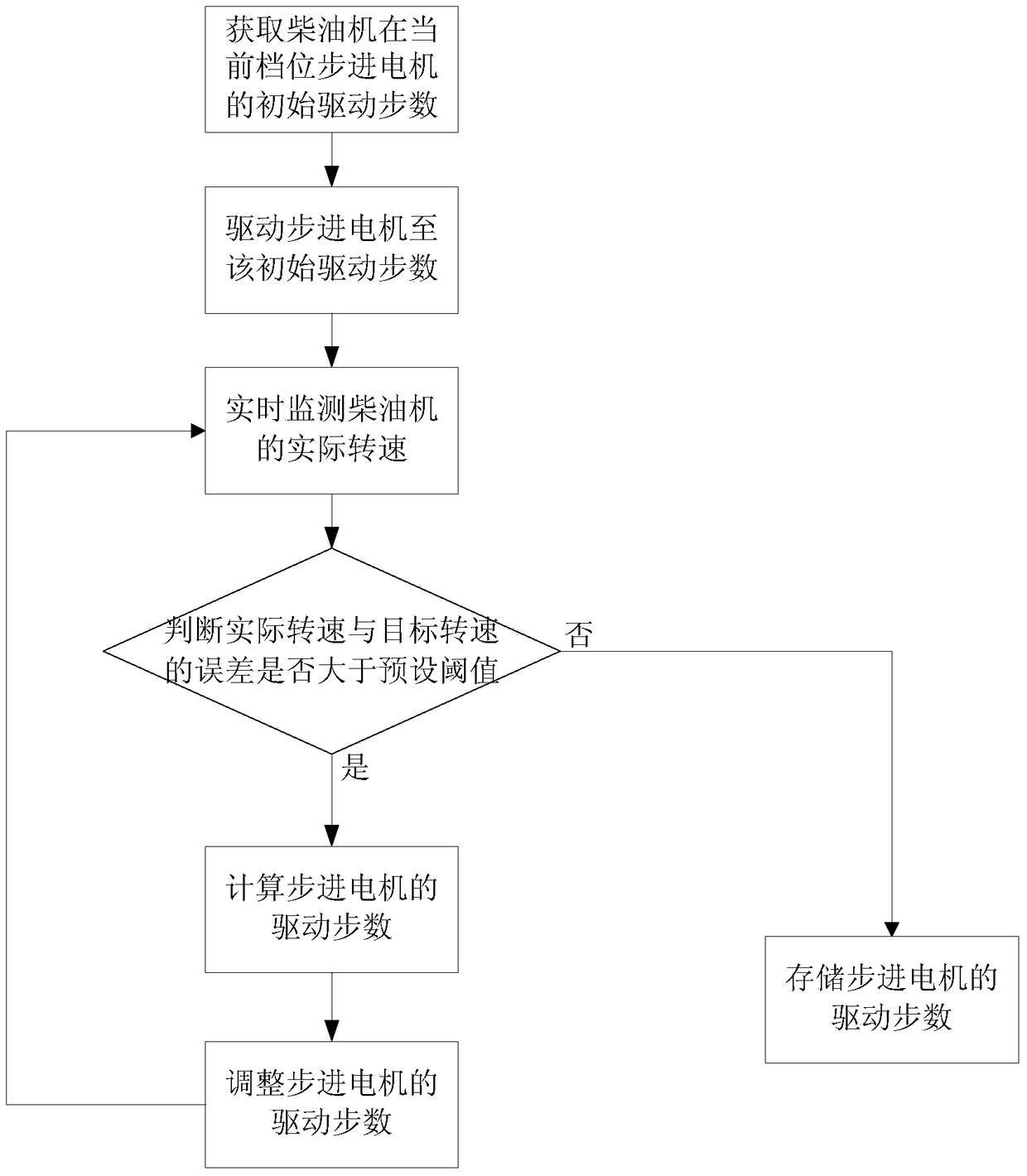
[0032] like figure 1 As shown, an adaptive diesel engine stepping speed regulation method of the present invention, its specific implementation process is as follows:

[0033] In this embodiment, the maximum gear number M of the diesel engine is set to be 16 gears, and the empirical theoretical estimate of the initial driving steps of the stepping motor in this gear is 900 steps. After the diesel engine is started, when the gear position changes, The adaptive speed regulation process of the stepper motor is as follows:

[0034] Adjust the gear position of the diesel engine controller to N gear, and follow the steps below to obtain the initial driving steps of the stepper motor and drive the stepper motor:

[0035] S1.1a. Read the value U stored in the diesel eng...


PUM


Abstract

The invention discloses a step-by-step speed regulation method for an adaptive diesel engine, which comprises the following steps: S1. Acquiring the initial driving steps of the stepping motor in the current gear of the diesel engine, and driving the stepping motor to the initial stepping number; S2. Monitoring The actual speed of the diesel engine, judging whether the error between the actual speed and the preset target speed of the diesel engine in the current gear is greater than the preset threshold, if it is greater, jump to step S3, otherwise jump to step S4; S3. Calculation The number of driving steps of the stepping motor, and adjust the number of driving steps of the stepping motor of the diesel engine in the current gear, and jump to step S2; S4. Store the driving steps of the stepping motor of the diesel engine in the current gear to the stepping speed regulation of the diesel engine system. The invention can quickly and accurately automatically adjust when the rotational speed of the diesel engine does not meet the standard, meets the overall performance requirements of the diesel engine, has good control effect, is convenient for debugging, and is economical and durable.

Description

technical field [0001] The invention relates to the field of diesel engine speed regulation control, in particular to an adaptive step-by-step speed regulation method for a diesel engine of a diesel locomotive. Background technique [0002] At present, the domestic microcomputer-controlled diesel engine stepping speed regulation system mainly adjusts the speed of the diesel engine through the driver controller. , so as to change the pre-tightening force of the speed regulating spring, so that the equipment connected to the rear end of the speed regulating spring is changed accordingly, the position of the speed regulating fuel supply rod, and the fuel supply of the diesel engine are controlled to achieve the purpose of adjusting the speed of the diesel engine. [0003] In actual control, since the speed-adjusting springs are nonlinear tower springs with similar parameters, the parameters of different speed-adjusting springs are not completely the same, which leads to errors ...

Claims


Application Information

Patent Timeline
Patent Type & Authority Patents(China)
IPC IPC(8): F02D1/12
Inventor 鲍睿李玮斌张东方郜永涛吴柏华李小文刘晨勇
Owner ZHUZHOU CSR TIMES ELECTRIC CO LTD
Why Eureka
Try Eureka