Gas turbine combustion system online monitoring method based on exhaust temperature measuring point correlation

A combustion system and correlation technology, applied in combustion methods, combustion chambers, combustion equipment, etc., can solve problems such as inability to realize early warning of combustion systems

Active Publication Date: 2015-12-02
NANJING POWER HORIZON INFORMATION TECH CO LTD
View PDF6 Cites 5 Cited by
  • Summary
  • Abstract
  • Description
  • Claims
  • Application Information

AI Technical Summary

Problems solved by technology

[0011] The present invention is to solve the problem that the prior art cannot realize the early warning of the combustion system, and pr

Method used


Image

  • Gas turbine combustion system online monitoring method based on exhaust temperature measuring point correlation
  • Gas turbine combustion system online monitoring method based on exhaust temperature measuring point correlation
  • Gas turbine combustion system online monitoring method based on exhaust temperature measuring point correlation

Examples


specific Embodiment approach 1

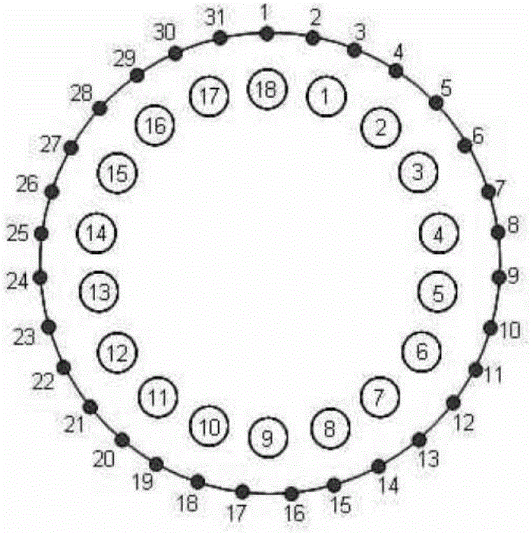
[0035] Specific implementation mode 1: An online monitoring method of gas turbine combustion system based on the correlation of exhaust temperature measurement points in this implementation mode is specifically implemented according to the following steps:

[0036] Step 1. Arrange n temperature measuring points evenly in the circumferential direction of the exhaust end of the gas turbine, and the temperature measured by the n temperature measuring points at time t is T t1 , T t2 ,...,T tn ;

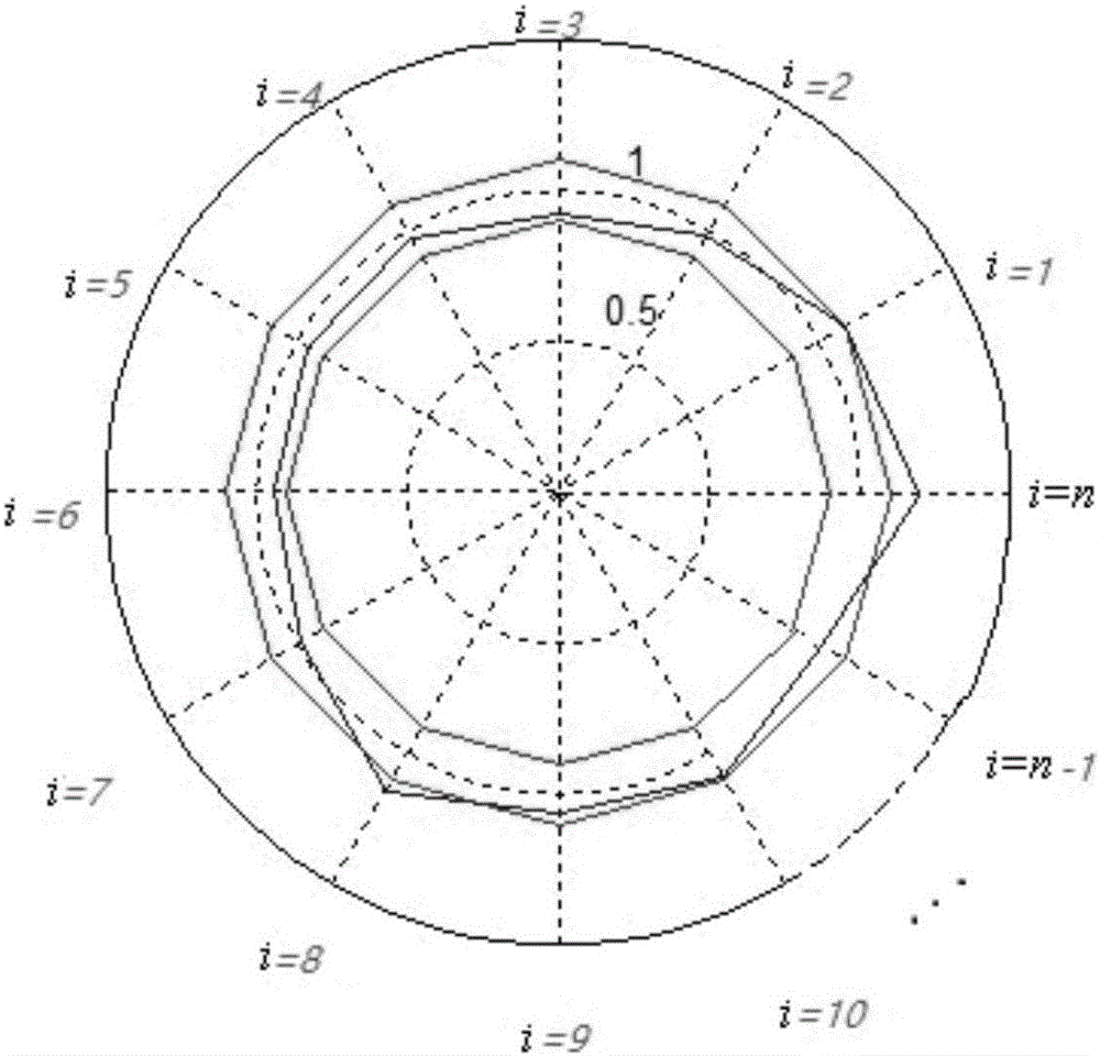
[0037] Step 2. During the period of normal operation of the gas turbine unit t 1 ~t 2 (The temperature measured at the temperature measuring point is t 1 ~t 2 The temperature at a limited number of moments, the specific number is related to the sampling frequency), according to the temperature T measured at time t by n temperature measuring points t1 , T t2 ,...,T tn , T t1 , T t2 ,...,T tn average temperature And the i-th temperature measuring point is at t 1 ~t 2 The aver...

specific Embodiment approach 2

[0057] Specific implementation mode two: the difference between this implementation mode and specific implementation mode one is: in step five, α i1 =μ i -3σ i , μ i is the mathematical expectation, σ i is the standard deviation. Other steps and parameters are the same as those in Embodiment 1.

specific Embodiment approach 3

[0058] Specific implementation mode three: the difference between this implementation mode and specific implementation mode one or two is: in step five, α i2 =μ i +3σ i , μ i is the mathematical expectation, σ i is the standard deviation. Other steps and parameters are the same as those in Embodiment 1 or Embodiment 2.


PUM


Abstract

The invention discloses a gas turbine combustion system online monitoring method based on an exhaust temperature measuring point correlation. The invention relates to the gas turbine combustion system online monitoring method. The invention mainly aims at solving a problem that early warning for a combustion system cannot realized in the prior art, and discloses the gas turbine combustion system online monitoring method based on the exhaust temperature measuring point correlation. The method comprises following steps: 1, achieving the temperature of n temperature measuring points at the time t; 2, obtaining a-hat and b-hat according to the temperature of the n temperature measuring points at the time t; 3, determining the [Ti]'-hat according to the a-hat and the b-hat obtained in the step 2; 4, defining the relation coefficient [alpha]i according to a formula that [alpha]i = [Ti]'-hat/T-hat; 5, setting the range of the [alpha]i being [[alpha]i1, [alpha]i2]; and 6, drawing dots with the upper limit [alpha]i1, the lower limit [alpha]i2 and the [alpha]i being polar radiuses and with (2[pi]*i)/n being the polar angle in polar coordinates, sequentially connecting the dots drawn from i=1 to i=n by straight lines, and connecting the dot drawn when i=1 and the dot drawn when i=n by a straight line, so that an enclosed polygon is obtained. If the range of the polar radius [alpha]i is [[alpha]i1, [alpha]i2], a gas turbine is in a normal operation state. The monitoring method is applicable to the field of gas turbine combustion system online monitoring.

Description

technical field [0001] The invention relates to an online monitoring method of a gas turbine combustion system, in particular to an online monitoring method of a gas turbine combustion system based on the correlation of exhaust temperature measurement points. Background technique [0002] With the advancement of technology, the gas turbine has become one of the core power equipment in the 21st century due to its advantages of compact structure, fast start-up, stable operation and high thermal efficiency. Anomaly detection and fault diagnosis technology is an important means to ensure the safe operation of gas turbines. The combustion chamber is an important part of the gas turbine. Its working conditions are harsh, failures occur frequently, and once damaged, the consequences are very serious. Therefore, it is of great significance to strengthen the abnormal detection and fault diagnosis of the combustion chamber. [0003] However, due to the extremely high temperature when...

Claims


Application Information

Patent Timeline
IPC IPC(8): F23M11/04
Inventor 刘金福刘娇万杰王彦飞李飞于达仁
Owner NANJING POWER HORIZON INFORMATION TECH CO LTD
Why Eureka
Try Eureka