
Method and device for identifying model parameters of vibrating mirror scanning motor

A motor model and galvanometer scanning technology, applied in the field of optical applications, can solve the problems of difficult implementation of motor control systems, slow convergence speed, and low identification accuracy.

Active Publication Date: 2017-11-07
北京市汉华环球科技发展有限责任公司
View PDF3 Cites 0 Cited by
  • Summary
  • Abstract
  • Description
  • Claims
  • Application Information

AI Technical Summary

Problems solved by technology

[0006] The purpose of the present invention is to provide a method for identifying the model parameters of the vibrating mirror scanning motor system that can improve the speed and accuracy of the parameter identification of the vibrating mirror scanning motor system, so as to solve the problems of difficult implementation, slow convergence speed and low identification accuracy in the motor control system in the background technology. question

Method used


Image

  • Method and device for identifying model parameters of vibrating mirror scanning motor
  • Method and device for identifying model parameters of vibrating mirror scanning motor
  • Method and device for identifying model parameters of vibrating mirror scanning motor

Examples


Embodiment Construction

[0060] Reference will now be made in detail to the exemplary embodiments, examples of which are illustrated in the accompanying drawings. When the following description refers to the accompanying drawings, the same numerals in different drawings refer to the same or similar elements unless otherwise indicated. The implementations described in the following exemplary examples do not represent all implementations consistent with the present invention. Rather, they are merely examples of apparatuses and methods consistent with aspects of the invention as recited in the appended claims.

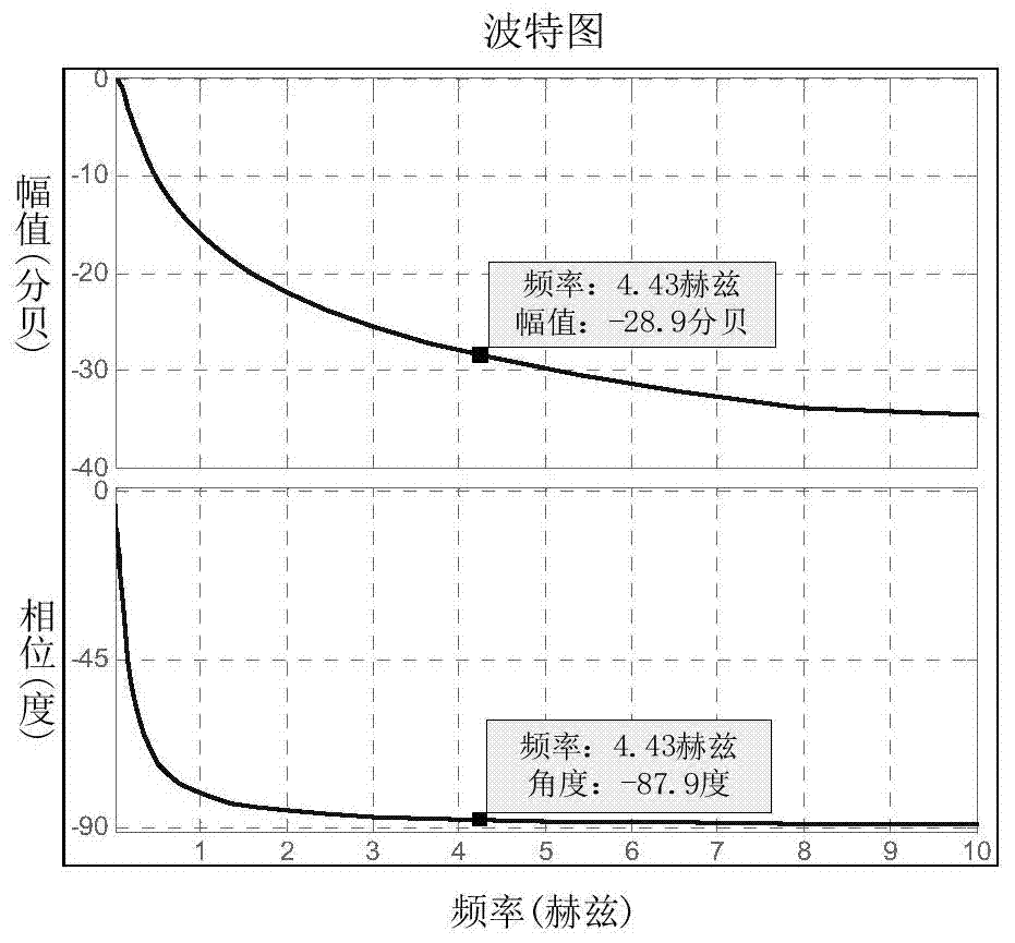
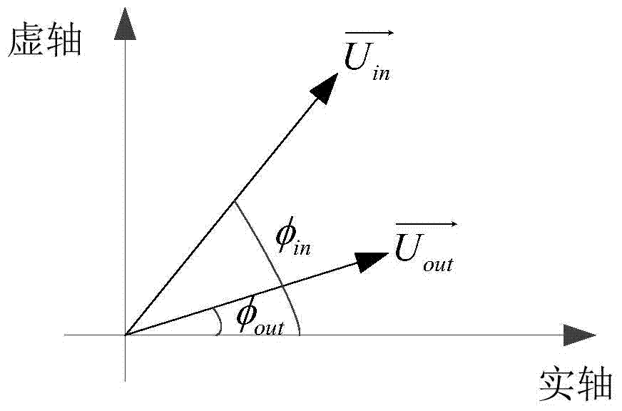
[0061] The inventors of the present invention have found that: when a sine (or cosine) signal of a certain frequency passes through the linear first-order inertia link, the output signal of the linear first-order inertia link is a sine (or cosine) signal with the same frequency as the input signal, but the output The phase and amplitude of the sine (or cosine) signal will change, and the amount ...


PUM


Abstract

The invention discloses an identification method and device for galvanometer scanning motor model parameters. The identification method and device for galvanometer scanning motor model parameters includes the following steps that: a general mathematical model including a stator coil unit, a rotor, a load unit and an integral unit which are connected with one another sequentially is established; first periodic voltage signals are utilized to excite a target motor when the target motor is in a locked-rotor state, outputted first current signals are sampled; sinusoidal components in the first periodic voltage signals and the first current signals are converted into first excitation voltage vectors and first current vectors, and the first excitation voltage vectors and first current vectors are introduced into the mathematical model, and the parameters of the stator coil unit are calculated; when the target motor is in a non-locked-rotor state, second periodic voltage signals are utilized to excite the target motor, and outputted second current signals and second motor position signals are sampled; sinusoidal components in the second current signals and the second motor position signals are extracted and converted into second current vectors and second motor position vectors, and the second current vectors and second motor position vectors are introduced to the mathematical model, and the parameters of the rotor and the load unit are calculated.

Description

technical field [0001] The invention relates to the field of optical applications, in particular to a method and device for identifying model parameters of a vibrating mirror scanning motor. Background technique [0002] The vibrating mirror scanning motor (hereinafter referred to as the motor) is a special DC brushless motor whose load is a mirror or an imaging device. Compared with traditional motors, its rated power is small, its dynamic response is fast, and its rotatable angle range is generally between -20° and +20°. Therefore, in the field of optical applications, this motor is usually used as a device to change the rotation angle of the optical path. device. [0003] In practical applications, in order to realize fast positioning control of the rotation angle of the motor, it is necessary to use the motor controller to perform closed-loop control (servo control) on the motor. Traditional motor controllers include analog controllers and PID (proportional-integral-de...

Claims


Application Information

Patent Timeline
Patent Type & Authority Patents(China)
IPC IPC(8): G01R31/34
Inventor 冯伟李言
Owner 北京市汉华环球科技发展有限责任公司
Learn More