
An oscilloscope analog front-end impedance conversion circuit with program-controlled correction function

A technology of impedance transformation circuit and oscilloscope, which is applied in the direction of instruments, measurement of electric variables, digital variable display, etc. It can solve the problems of inconvenient production and debugging, affecting the static collector current of transistors in the impedance transformation circuit, and affecting the size of AC gain, etc., and achieves convenience. The effect of production debugging

Inactive Publication Date: 2017-10-31
UNIV OF ELECTRONICS SCI & TECH OF CHINA
View PDF7 Cites 2 Cited by
  • Summary
  • Abstract
  • Description
  • Claims
  • Application Information

AI Technical Summary

Problems solved by technology

[0025] 1. It is necessary to manually adjust the adjustable resistance R 5 , once it is found that it is not corrected, it is necessary to disassemble the machine and recalibrate the hardware, which will bring inconvenience to production debugging;
[0026] 2. The circuit requires the post-stage load R L stable, if the post-stage load R L Unstable, it will affect the quiescent collector current of the transistor in the impedance transformation circuit, thereby affecting the AC gain, which destroys the consistency of the DC gain and the AC gain, and the adjustable resistor R has to be readjusted 5 , so, the traditional adjustment adjustable resistor R 5 approach, not suitable for post-stage load R L occasions of dynamic change

Method used


Image

  • An oscilloscope analog front-end impedance conversion circuit with program-controlled correction function
  • An oscilloscope analog front-end impedance conversion circuit with program-controlled correction function
  • An oscilloscope analog front-end impedance conversion circuit with program-controlled correction function

Examples


Embodiment Construction

[0045] Specific embodiments of the present invention will be described below in conjunction with the accompanying drawings, so that those skilled in the art can better understand the present invention. It should be noted that in the following description, when detailed descriptions of known functions and designs may dilute the main content of the present invention, these descriptions will be omitted here.

[0046] In this example, if Figure 5 Shown, the present invention has the oscilloscope analog front-end impedance transformation circuit of program-controlled calibration function and prior art scheme (such as Figure 4 shown) The difference is that the programmable current source is added, and the bias adjustment resistor R 5 Being a fixed value resistor rather than an adjustable resistor, it can be controlled by software program to achieve consistent calibration of DC gain and AC gain. Even when the impedance transformation circuit post-stage load R L (Program-controll...


PUM


Abstract

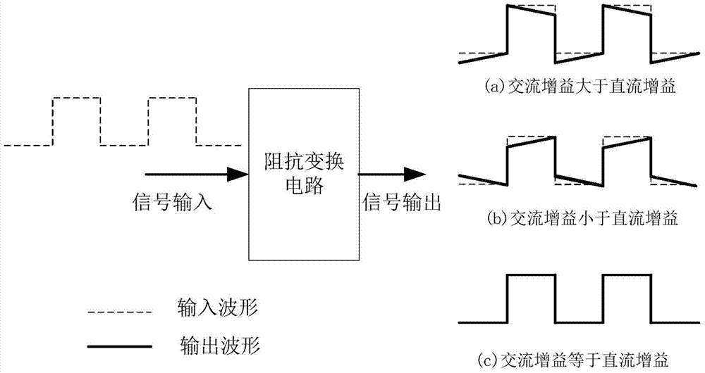
The invention discloses an oscilloscope analog front-end impedance transformation circuit with a program-controlled calibration function. A program-controlled current source to a negative power supply is added to the emitter of a high-frequency crystal triode. Under the condition that the DC gain remains unchanged, the current of the program-controlled current source is adjusted through the program control, thereby adjusting the emitter current of the high-frequency transistor of the output stage in the impedance transformation circuit, so that the AC gain of the impedance transformation circuit is equal to the DC gain. Before leaving the factory, the current of the program-controlled current source is adjusted so that the AC gain of the impedance conversion circuit is equal to the DC gain. There is no need to manually adjust the bias resistance, and it is not necessary to disassemble the machine, which is convenient for production and debugging. In addition, when the input static resistance of the post-stage programmable variable gain circuit changes, it can be dynamically adjusted, which overcomes the prior art and is not suitable for the situation where the post-stage load RL changes dynamically.

Description

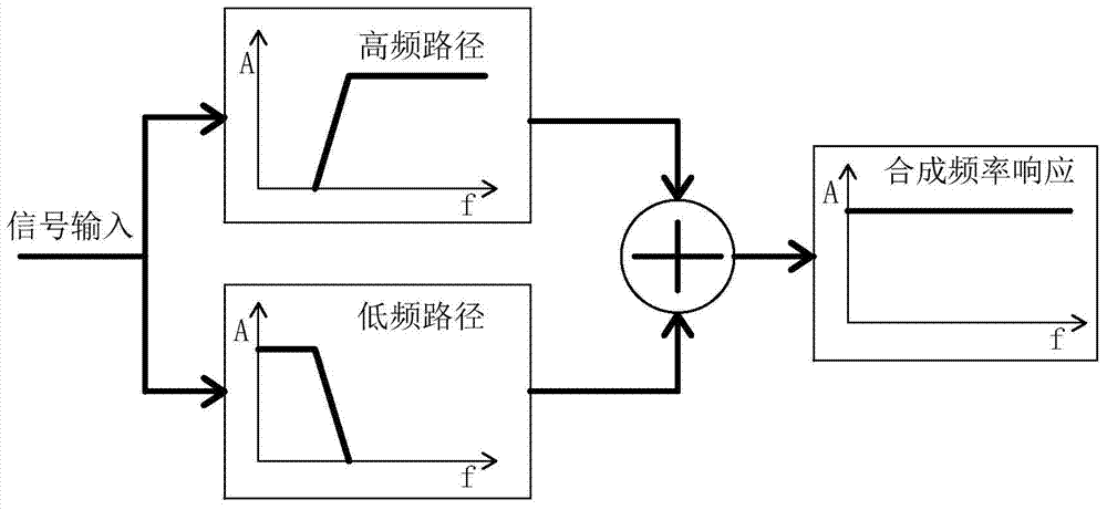
technical field [0001] The invention belongs to the technical field of analog signal conditioning in high-speed data acquisition, and more specifically relates to an oscilloscope analog front-end impedance conversion circuit with a program-controlled calibration function, which can calibrate the low-frequency square wave distortion of the circuit through a software program, thereby realizing DC Consistency correction for gain and AC gain. Background technique [0002] The analog signal conditioning front-end circuit is an indispensable and important part of many data acquisition systems. It is used to realize functions such as signal amplification or attenuation, impedance transformation, and bias adjustment, so as to realize accurate quantitative measurement of the measured signal. In a digital oscilloscope, a general-purpose electronic test instrument, it is necessary to test various complex broadband signals, so its frequency response covers DC signals and high-frequency ...

Claims


Application Information

Patent Timeline
Patent Type & Authority Patents(China)
IPC IPC(8): G01R35/02G01R13/02
Inventor 邱渡裕谭峰姚龙飞郭连平曾红林
Owner UNIV OF ELECTRONICS SCI & TECH OF CHINA
Learn More