
Long-focal-depth and deep-sub-wavelength-focused one-dimensional photonic crystal flat cone mirror for column vector beams

A one-dimensional photonic crystal, deep subwavelength technology, applied in optics, optical components, instruments, etc., can solve the problems of limiting the use range of the optical needle focal field, not discussing the focusing of handed polarized light, etc., and achieves a simple design method, The effect of evenly distributed focus

Active Publication Date: 2015-12-02
NANJING UNIV OF POSTS & TELECOMM
View PDF5 Cites 10 Cited by
  • Summary
  • Abstract
  • Description
  • Claims
  • Application Information

AI Technical Summary

Problems solved by technology

In the method of focusing with a mirror with a parabolic surface, the incident light and the reflected light are located on the same side of the mirror, which limits the scope of use of the optical needle-shaped focal field
The above two methods of long focal depth focusing are only for radially polarized light, and do not discuss the focusing of circularly polarized light

Method used


Image

  • Long-focal-depth and deep-sub-wavelength-focused one-dimensional photonic crystal flat cone mirror for column vector beams
  • Long-focal-depth and deep-sub-wavelength-focused one-dimensional photonic crystal flat cone mirror for column vector beams
  • Long-focal-depth and deep-sub-wavelength-focused one-dimensional photonic crystal flat cone mirror for column vector beams

Examples


Embodiment Construction

[0017] The present invention is described in detail below in conjunction with accompanying drawing and embodiment, and present embodiment is carried out under the premise of technical scheme of the present invention, has provided detailed embodiment and specific operation process, but protection scope of the present invention is not limited to the following the described embodiment.

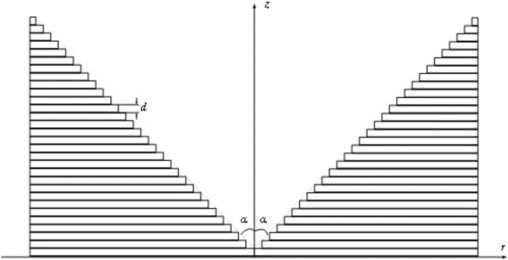
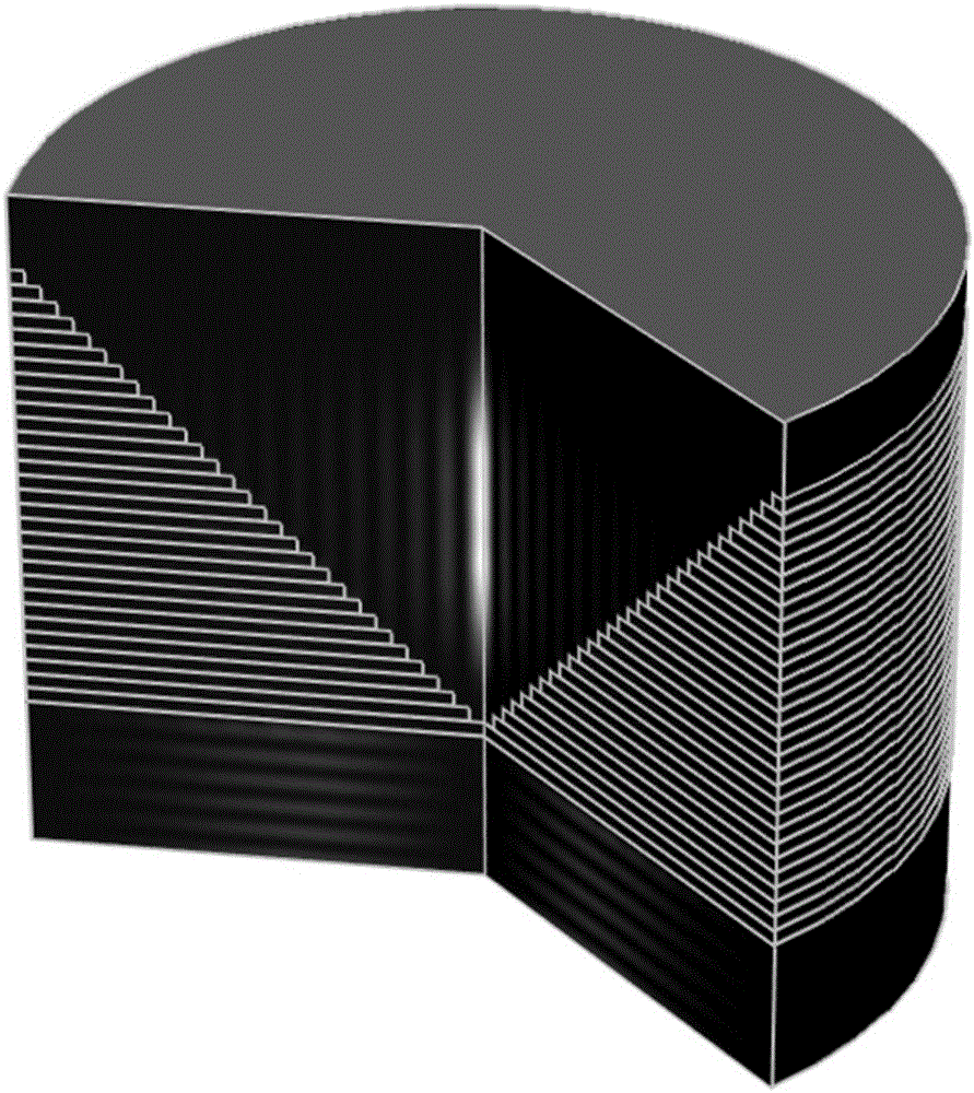
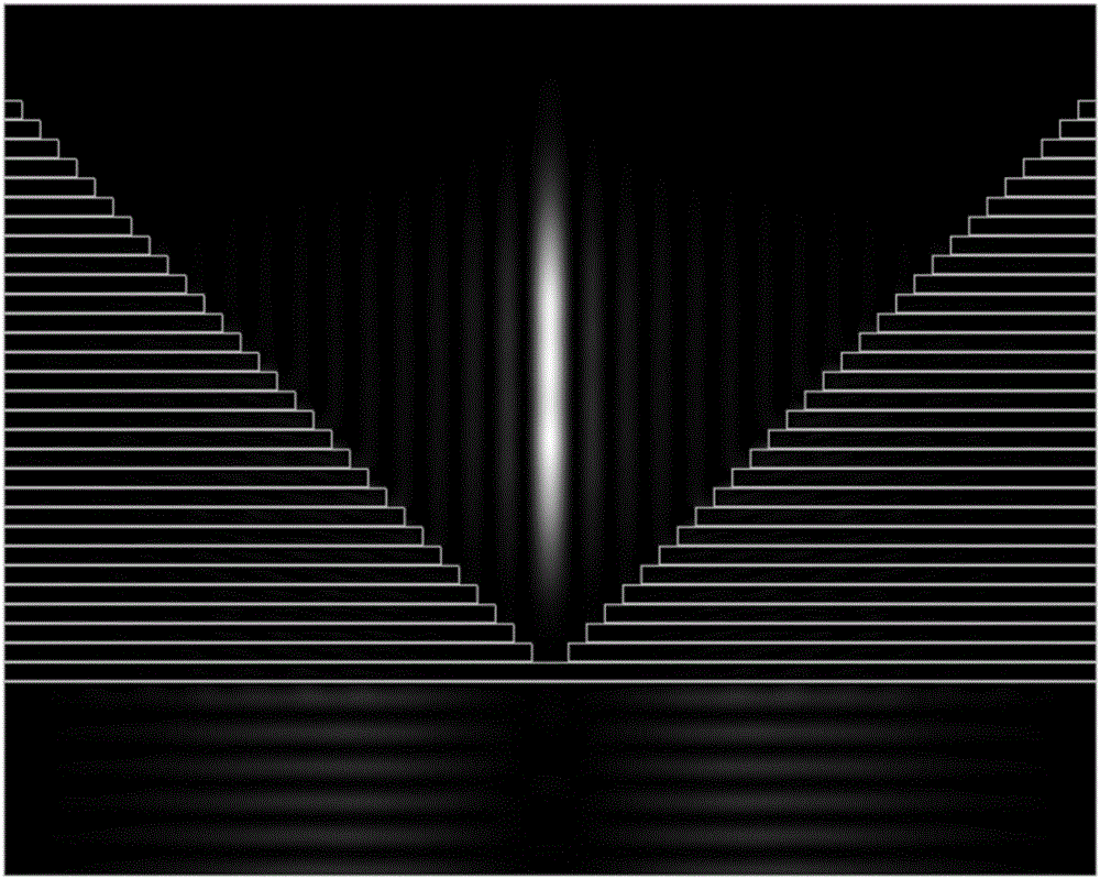
[0018] Such as figure 1 As shown, this embodiment is a one-dimensional photonic crystal conical mirror composed of materials A and B alternately arranged, and the incident light is in a bessel-gauss distribution with a frequency of λ 0 = 532nm. In order for the photonic crystal to include λ 0 =532nm has a negative refractive index n in the band, and the selected material 1 is MgF by calculation 2 , Material 2 is GaN. Period d=a+b of one-dimensional photonic crystal conical mirror, a is MgF 2 thickness, b is the thickness of GaN, its values ​​are 10nm and 140nm, combined with MgF 2 The refra...


PUM


Abstract

The invention discloses a long-focal-depth and deep-sub-wavelength-focused one-dimensional photonic crystal flat cone mirror for column vector beams. The one-dimensional photonic crystal flat cone mirror is composed of one-dimensional photonic crystals formed through the alternate arrangement of a material A and a material B. The emitting surface of the flat cone mirror is in the form of an inverted cone-shaped surface. The inverted cone-shaped surface is not a continuous cone-shaped surface, wherein circular rings of fixed thickness are stacked up to form the inverted cone-shaped surface, with one cycle (d) of the photonic crystals as one unit and the internal diameters of the circular rings being gradually and equivalently increased from bottom to top. The inner sides of the circular rings are in the form of a vertical wall, and the connecting line of the vertex angles of the circular rings is at an included angle relative to the horizontal plane. By means of the flat cone mirror, radially polarized beams and rotatably polarized beams are focused at the same time, so that light needle-shaped focuses and light pipe-shaped focuses that are uniformly distributed in the longitudinal field can be respectively obtained. Through changing the structural parameters of photonic crystals, the wide-band focusing is realized. Meanwhile, through stretching out or drawing back the flat cone mirror, the length of the focal depth can be controlled. The flat cone mirror is simple in structure, and simple and convenient in design process. The structure of the flat cone mirror can be easily prepared. Therefore, the flat cone mirror is good in application prospect in the fields of near-field optics, laser processing, medical science and the like.

Description

technical field [0001] The invention relates to an artificial microstructure material used in the fields of sub-wavelength photonics, optical micro-manipulation, etc., in particular to a one-dimensional photonic crystal conical mirror used for long-focusing and deep-subwave focusing of cylindrical vector beams. Background technique [0002] As the most basic optical tool, lens plays an important role in optical microscope, high-density optical storage, laser engraving and other fields. With the development of science and technology, many fields are developing toward high integration and high density, and at the same time, higher requirements are put forward for the focusing spot of optical components. Cylindrical vector beams, as a kind of vector beams, have unique application ranges different from scalar beams due to their symmetry in cylindrical coordinates, and have shown potential application value in many fields. Cylindrical vector beams can be classified into radially...

Claims


Application Information

Patent Timeline
Patent Type & Authority Applications(China)
IPC IPC(8): G02B5/00
CPCG02B5/001
Inventor 许吉王胜明万洪丹仲义任蓉王瑾
Owner NANJING UNIV OF POSTS & TELECOMM
Learn More