A kind of plc control system and plc expansion bus realization method

A technology for expanding the bus and control system, applied in general control systems, control/regulation systems, program control, etc., can solve problems such as poor anti-interference ability, prone to errors, and impermissibility, etc., and achieve strong anti-interference ability and high data speed The effect of improving and stabilizing data

Active Publication Date: 2018-04-03
深圳市合信自动化技术有限公司
View PDF5 Cites 0 Cited by
  • Summary
  • Abstract
  • Description
  • Claims
  • Application Information

AI Technical Summary

Problems solved by technology

[0003] Existing PLCs and expansion modules are connected and communicated with expansion buses such as serial peripheral interface (serial peripheral interface, SPI) or controller area network bus (Controller Area Network, CAN), but in the prior art, in In some cases, the rate of the expansion bus itself is relatively high. Under the requirement of low cost (for example, the microprocessor using LCMO2), because the system does not allow higher frequency multiplication, there is no way to realize the data transmitted between the PLC and the expansion module. For multiple sampling and filtering processing, only single-point sampling can be performed, so errors are prone to occur and the anti-interference ability is poor

Method used


Image

  • A kind of plc control system and plc expansion bus realization method
  • A kind of plc control system and plc expansion bus realization method
  • A kind of plc control system and plc expansion bus realization method

Examples


Embodiment Construction

[0045] Embodiments of the present invention will be described in detail below in conjunction with the accompanying drawings.

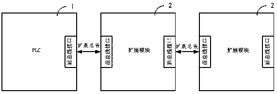
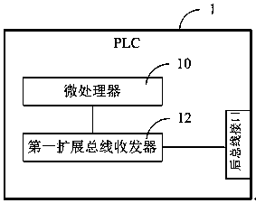
[0046] Such as figure 1 As shown in FIG. 1 , a schematic structural diagram of an embodiment of a PLC control system provided by the present invention is shown. In this embodiment, the PLC control system includes a PLC1 and a plurality of expansion modules 2, and the expansion bus is used to cascade between the PLC1 and the plurality of expansion modules 2 to form a bus topology; wherein, in one embodiment, in this In one embodiment of the invention, the expansion bus adopts MLVDS (Multipoint low Voltage Differential Signaling, multi-point low voltage differential signal) expansion bus, and the MLVDS bus belongs to the half-duplex communication of bus type topology, and the expansion bus mentioned later All are described with the MLVDS extension bus, but it should be understood that in other embodiments, other types of buses may also be used. The exp...


PUM


Abstract

The invention discloses a PLC control system, which comprises a PLC and a plurality of extension modules, wherein the PLC is cascaded with the plurality of extension modules by adopting extension buses; the PLC comprises a microprocessor and a first extension bus transceiver, the microprocessor is used for controlling communication between the PLC and the plurality of extension modules, and the first extension bus transceiver is used for exchanging data with the first stage extension module through a PLC rear bus interface; and each extension module comprises an extension microprocessor and a second extension bus transceiver, the extension microprocessor is used for controlling communication between the extension module and the PLC, and the second extension bus transceiver is used for exchanging data with the previous stage extension module or the PLC through a corresponding stage front bus interface and exchanging data with the next stage extension module through a corresponding stage rear bus interface. The invention further discloses a corresponding PLC extension bus implementation method. Through implementing the technical scheme of the invention, the speed of a PLC extension bus can be increased, the cost is reduced, and the anti-interference capability in the sampling process is high.

Description

technical field [0001] The present invention relates to the field of programmable logic controller (Programmable Logic Controller, PLC), in particular to a PLC control system and a PLC expansion bus implementation method. Background technique [0002] In the prior art, PLC is to expand I / O (Input / Output, input or output) points or functions. Generally, various I / O modules or functional modules need to be connected through an expansion bus to form a PLC control system. The expansion bus communicates with I / O modules or function modules. [0003] Existing PLCs and expansion modules are connected and communicated with expansion buses such as serial peripheral interface (serial peripheral interface, SPI) or controller area network bus (Controller Area Network, CAN), but in the prior art, in In some cases, the rate of the expansion bus itself is relatively high. Under the requirement of low cost (for example, the microprocessor using LCMO2), because the system does not allow hig...

Claims


Application Information

Patent Timeline
Patent Type & Authority Patents(China)
IPC IPC(8): G05B19/05
CPCG05B19/05G05B2219/25268
Inventor 黄诚雄
Owner 深圳市合信自动化技术有限公司
Why Eureka
Try Eureka