a rescue device
A microphone and speaker technology, applied in the direction of electrical transmission signal system, etc., can solve the problems of death of children, hidden dangers of total closure, difficult to break the window to escape and other problems, and achieve the effect of increasing the probability of rescue, simple structure and strong practicability.
- Summary
- Abstract
- Description
- Claims
- Application Information
AI Technical Summary
Problems solved by technology
Method used
Image
Examples
no. 1 example
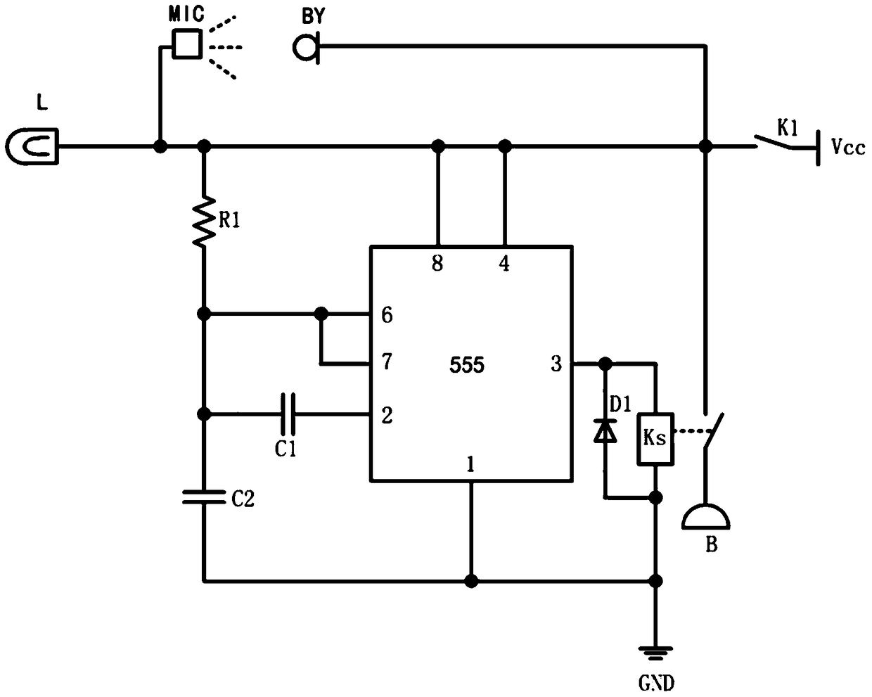
[0032] Please refer to figure 1 , figure 1It shows a schematic circuit diagram of the emergency calling device provided by the first embodiment of the present invention. The emergency calling device provided by the first embodiment of the present invention can be applied to automobiles. The emergency calling device provided by the first embodiment of the present invention includes a switch K1, a microphone MIC, a speaker BY and the warning light L, the speaker BY and the warning light L are arranged outside the car, the switch K1 and the microphone MIC are located in the car, the microphone MIC is coupled with the speaker BY, the switch K1 is electrically connected to the microphone MIC and the speaker BY, respectively, and the warning light L is electrically connected to the microphone MIC.
[0033] Among them, the switch K1 can be a button switch K1, or a toggle switch K1, the data transmission between the microphone MIC and the speaker BY can be realized through wired or w...
no. 2 example
[0036] Please refer to figure 2 , figure 2 It shows the schematic circuit diagram of the emergency calling device provided by the second embodiment of the present invention. Compared with the first embodiment, the improvement point of this embodiment is that it also includes a prompting circuit unit for prompting false touches, and the prompting circuit unit It is used to remind the person in the car that the switch has been turned on when the person in the car touches the switch by mistake.
[0037] The prompt circuit unit includes a delay chip, a first resistor R1, a first capacitor C1, a second capacitor C2, a first diode D1, a relay Ks, a metal sheet S and a buzzer B, and the power supply is connected to one end of the switch K1 , the other end of the switch K2 is connected to a contact of the relay Ks, the other contact of the relay Ks is connected to the buzzer B, and the other end of the switch K1 is connected to the delay chip at the same time The reset pin, the po...
no. 3 example
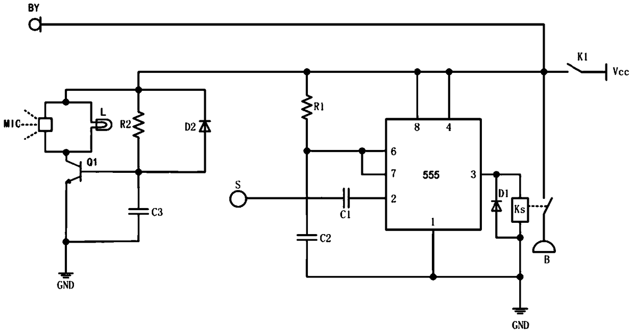
[0042] Please refer to image 3 , image 3 It shows the schematic circuit diagram of the emergency calling device provided by the third embodiment of the present invention. Compared with the second embodiment, the improvement of this embodiment is that it also includes a microphone delay start circuit unit, and the microphone delay start circuit unit can be When the buzzer B in the prompt circuit is working, the microphone MIC is not working, and when the buzzer B stops working, the microphone MIC is working again.
[0043] The microphone delay opening circuit unit includes a second resistor R2, a third capacitor C3, an NPN transistor Q1 and a second diode D2, one end of the switch K1 is connected to a power supply, and the other end of the switch K1 is connected to the second One end of the resistor R2, one end of the second resistor R2 is simultaneously connected to one end of the microphone MIC, one end of the warning light L, and the cathode of the second diode D2, and th...
PUM
 Abstract
Description
Claims
Application Information
 - R&D
- Intellectual Property
- Life Sciences
- Materials
- Tech Scout
- Unparalleled Data Quality
- Higher Quality Content
- 60% Fewer Hallucinations
Browse by: Latest US Patents, China's latest patents, Technical Efficacy Thesaurus, Application Domain, Technology Topic, Popular Technical Reports.
© 2025 PatSnap. All rights reserved.Legal|Privacy policy|Modern Slavery Act Transparency Statement|Sitemap|About US| Contact US: help@patsnap.com


