Treatment tool

A technology for processing instruments and manipulators, which is applied to anatomical instruments, heating surgical instruments, parts of surgical instruments, etc.

Inactive Publication Date: 2015-12-02
OLYMPUS CORP
View PDF11 Cites 0 Cited by
  • Summary
  • Abstract
  • Description
  • Claims
  • Application Information

AI Technical Summary

Problems solved by technology

[0003] Since the rotating member provided on the first clamping member rotates, there is a danger that the rotating member itse

Method used


Image

  • Treatment tool
  • Treatment tool
  • Treatment tool

Examples


Embodiment Construction

[0037] Hereinafter, modes for implementing the present invention will be described with reference to the drawings.

[0038] refer to Figure 1 to Figure 7 The first embodiment will be described.

[0039] Here, as a treatment instrument (energy treatment instrument) for applying energy to living tissue for treatment, for example, a pull-wire type bipolar treatment instrument 12 for treatment through the abdominal wall will be described as an example. .

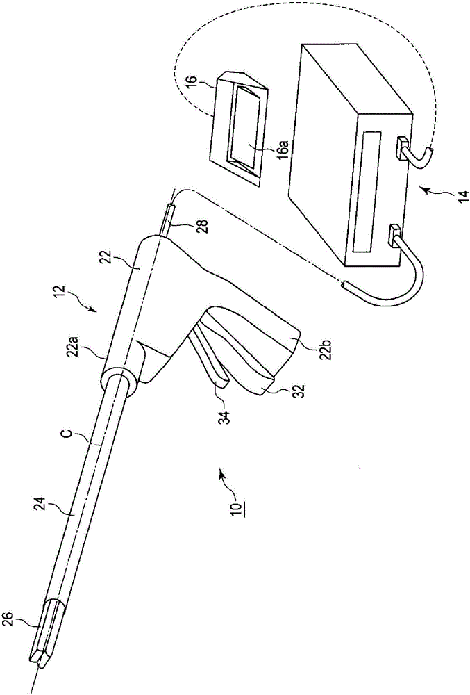
[0040] Such as figure 1 As shown, a therapeutic treatment system 10 includes a treatment implement (therapeutic treatment implement) 12, an energy source 14, and a foot switch 16 having a pedal 16a.

[0041] The treatment implement 12 includes a handle 22 , a shaft 24 having a central axis C, and a treatment portion 26 . The energy source 14 is connected to the handle 22 by means of a cable 28 . A foot switch 16 is connected to the energy source 14 . When the operator (user) operates the pedal 16a of the foot switch 16 wi...


PUM


Abstract

A treatment instrument configured to treat living tissue by applying energy includes: first and second holding members; a swing member supported by the first holding member and being rotatable in a first direction and in a second direction opposite to the first direction on a rotation axis as a supporting point; a limiting portion which limits rotation of the swing member in one of the first and second directions; a first holding surface provided on the side of the swing member close to the second holding member and configured to hold living tissue; a second holding surface provided on the side of the second holding member close to the swing member and cooperating with the first holding surface of the swing member to hold the living tissue; and a protrusion forming a clearance between the first and second holding surfaces when the first and second holding surfaces are relatively closed.

Description

technical field [0001] The present invention relates to a treatment device for applying energy to living tissue and treating it. Background technique [0002] For example, US2010 / 0057117A1 discloses a first holding member that can be opened and closed relative to a second holding member (probe). The first clamping member is provided with a rotating member having a living tissue grasping surface for clamping the living tissue between the first clamping member and the second clamping member. Therefore, the living tissue can be grasped with a more uniform force between the living tissue grasping surface of the rotating member and the living tissue grasping surface of the second clamping member. [0003] Since the rotation member provided on the first clamping member rotates, there is a possibility that the rotation member itself or its living tissue grasping surface abuts against the living tissue grasping surface of the second clamping member. Contents of the invention [...

Claims


Application Information

Patent Timeline
IPC IPC(8): A61B18/12A61B17/3211
CPCA61B18/1445A61B18/1482A61B2017/2936A61B2017/2939A61B2018/00083A61B2018/00101A61B2018/1455A61B2019/305A61B18/085A61B2018/0063A61B2090/035
Inventor 傍岛秀雄高篠智之武井祐介
Owner OLYMPUS CORP
Why Eureka
Try Eureka