Engine control unit for a self-igniting internal combustion engine and method for operating a self-igniting internal combustion engine

An automatic ignition, internal combustion engine technology, applied in engine control, internal combustion piston engine, engine components, etc., can solve problems such as expensive, large number of components and control devices, and achieve cost-saving effects

Inactive Publication Date: 2015-12-02
SCHAEFFLER ENG
View PDF6 Cites 0 Cited by
  • Summary
  • Abstract
  • Description
  • Claims
  • Application Information

AI Technical Summary

Problems solved by technology

[0005] According to the prior art, the mixing of gaseous fuels requires complex gas supply installations which require a large number of components and controls and are therefore extremely expensive
In addition

Method used


Image

  • Engine control unit for a self-igniting internal combustion engine and method for operating a self-igniting internal combustion engine

Examples


Embodiment Construction

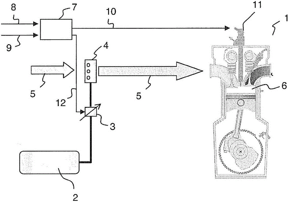
[0022] In addition to auto-ignition diesel fuel, internal combustion engines may also be used with a second non-auto-ignition fuel supply, for example comprising compressed natural gas (CNG). CNG is stored in fuel tank 2 . With the help of a pressure regulator 3 CNG can be supplied to a Venturi mixer 4 . The Venturi mixer 4 is integrated into the intake tract 5 of the internal combustion engine. Thus, combustion chamber 6 of cylinder 1 is supplied with a mixture of air, diesel fuel and CNG.

[0023] The composition of the air-fuel mixture is regulated by the engine control 7 in a closed loop or in an open control system. Like any conventional engine control device 7, this unit also includes several analog and digital input and output interfaces to sensors and brakes. In addition, a CAN bus interface (not shown) is provided on the engine control device 7 for communication with other control devices in the vehicle.

[0024] The input signals of the engine control unit 7 are ...


PUM


Abstract

The invention relates to a method for operating an internal combustion engine with autoignition capability using a first, autoignitable fuel and a second, non-autoignitable fuel. A self-igniting operation of said type is made considerably simpler in relation to the prior art by means of the following method steps: a) detecting a setpoint value change for the operation of the internal combustion engine which requires an increase of the fuel flow rate to be supplied to the internal combustion engine, b) increasing the flow rate of the first fuel supplied to the internal combusion engine to a value that effects a follow-up adjustment of the actual value associated with a setpoint value, wherein the supplied flow rate of the second fuel initially remains unchanged, c) newly calculating and controlling the flow rates of the first and second fuels to be supplied to the internal combustion engine such that the actual value continues to correspond to the setpoint value and the flow rate of the first fuel is reduced in relation to the flow rate determined in step b) but remains high enough to effect autoignition of the mixture of first and second fuel and air.

Description

technical field [0001] The invention relates to a device and a method for operating a so-called dual fuel engine. A dual-fuel engine in relation to the present invention is understood to be an internal combustion engine with auto-ignition that can be operated on at least two different fuels. Of the at least two different fuels, at least one is auto-igniting and at least one is non-auto-igniting. Background technique [0002] Auto-ignition internal combustion engines are characterized by compressing an air-fuel mixture until the fuel auto-ignites without the need for an external ignition source such as a spark plug. [0003] In the case of a dual fuel engine, the first auto-ignition fuel is mixed with a second non-auto-ignition fuel. This type of engine must be operated so that sufficient auto-ignition fuel present in the mixture is ignited due to compression to also cause non-auto-ignition fuel to burn. Thus, in this type of internal combustion engine with dual-fuel opera...

Claims


Application Information

Patent Timeline
IPC IPC(8): F02D19/10F02D41/10F02D41/00
CPCF02D19/10F02D41/0027F02D41/10F02D2200/602F02M21/047Y02T10/36Y02T10/30
Inventor 拉尔斯·皮弗泽尤尔迪尔克·诺伊鲍尔
Owner SCHAEFFLER ENG
Why Eureka
Try Eureka