Feed machine pendulum pellet feed stabilizer discharge mechanism

A pendulum-type granule and feed machine technology, applied in feed, food science, application, etc., can solve problems such as uneven batch ripening, high extrusion force, and impact on quality, so as to reduce the frequency of manual cleaning, reduce weight, and facilitate replacement Effect

Active Publication Date: 2017-01-18
HUBEI SANJIANG SPACE MECHANICAL & ELECTRICAL EQUIP
View PDF6 Cites 0 Cited by
  • Summary
  • Abstract
  • Description
  • Claims
  • Application Information

AI Technical Summary

Problems solved by technology

On the one hand, the L-shaped flap is a single layer. Although it is made of stainless steel, it is easily corroded by materials. After it is damaged, it needs to be replaced in time to prevent material leakage; on the other hand, the horizontal long end of the L-shaped flap is placed horizontally, and the pellets are on the side There are downward gravity extrusion and lateral side extrusion at the contact position. The extrusion force is large, and it is easy to make the material stick and agglomerate on the plane of the L-shaped flap. Entering the next batch of feed will seriously affect its feed quality
Although this pendulum-type discharge mechanism can open the door quickly, it cannot avoid a small amount of arching and adhesion. Once the charred material will affect the quality of the whole batch of material; and the temperature in the curing room is generally high, the light is dark, and the damage of the flap is not easy to find. The flap is a single layer, material leakage will lead to uneven batch ripening

Method used


Image

  • Feed machine pendulum pellet feed stabilizer discharge mechanism
  • Feed machine pendulum pellet feed stabilizer discharge mechanism
  • Feed machine pendulum pellet feed stabilizer discharge mechanism

Examples


Embodiment Construction

[0022] Below in conjunction with accompanying drawing and specific embodiment the present invention is described in further detail:

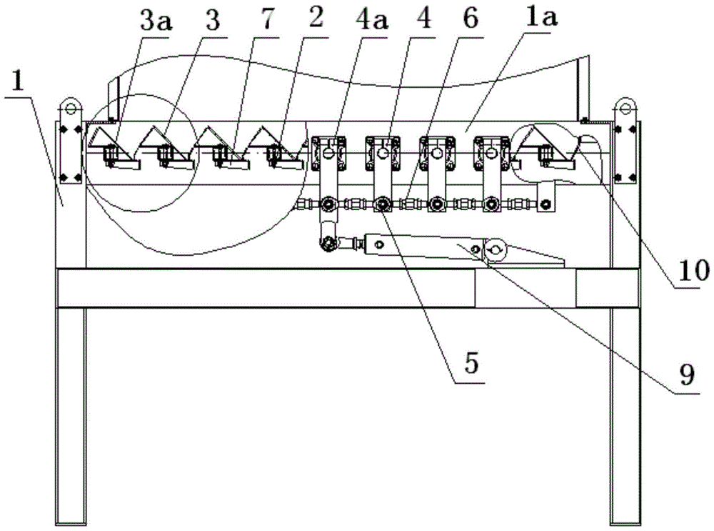
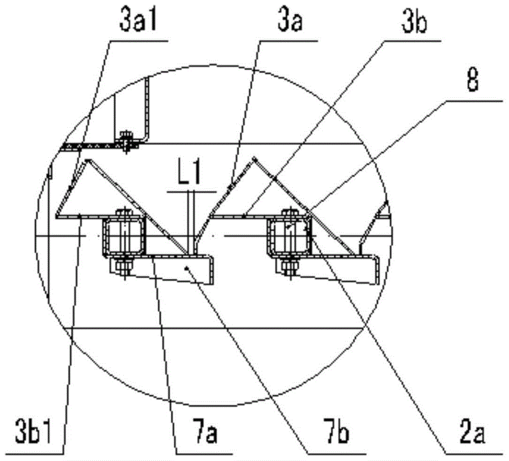
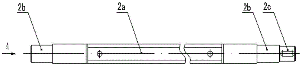
[0023] Such as figure 1 , figure 2 , image 3 , Figure 4 , Figure 5 , Figure 6 : a kind of feed machine pendulum pellet feed stabilizer discharging mechanism of the present invention comprises square frame assembly 1, utilizes bearing positioning to be installed on a row of shaft assemblies 2 on frame assembly 1 both sides side walls 1a, in each shaft assembly 2 is installed with a flap assembly 3 to form a front-to-back discharge unit, one end of the shaft assembly 2 is connected to the transmission link 4, the lower part of the transmission link 4 is connected to the joint bearing 5, and the joint bearing 5 of the adjacent transmission link 4 passes through The adjustment sleeve 6 is connected, and an active transmission link 4a in the transmission link 4 is connected with the hydraulic drive device 9; the flap assembly 3 and the supp...


PUM


Abstract

The present invention discloses a pendulous granulated feed stabilizer discharge mechanism of a feed machine. The mechanism comprises a square frame assembly. A row of shaft assemblies which are evenly distributed and arranged on both side walls of the square frame assembly are positioned by using bearings. One ends of the shaft assemblies are connected with drive connecting rods. The lower parts of the drive connecting rods are connected to knuckle bearings. The knuckle bearings of the adjacent drive connecting rods are connected by regulating sleeves. Turning plate assemblies and bearing plate assemblies are fixed on square steel tubes of the shaft assemblies. The turning plate assemblies include small turning plate assemblies and large turning plate assemblies. The large turning plate assemblies consist of arch upper turning plates at the upper part and trough lower turning plates at the lower part. The arch upper turning plates include front bevels and rear bevels. The trough lower turning plates comprise front bevel intermediate planes and rear vertical planes. Bevel discharge turning plates are formed by the connection of the front bevels, which have similar inclination angles, of the arch upper turning plates and the trough lower turning plates. The intermediate planes and vertical planes of the lower trough lower turning plates are wrapped and attached on the square steel tubes of the shaft assemblies. An adjustment plate is connected to the rear wall of the square frame assembly.

Description

technical field [0001] The invention relates to a pendulum stabilizer, in particular to a discharge mechanism for a pendulum pellet feed stabilizer of a feed machine. Background technique [0002] The pendulum stabilizer is a kind of post-curing and tempering equipment after the pellets are pressed and formed. It is mainly used for special aquatic feed pellets. Stability in water, improve feed digestibility. At present, the discharge mechanism of the pendulum stabilizer is generally driven by a hydraulic component to drive the long connecting rod and the multi-stage connecting rod to drive the short connecting rod, and the short connecting rod drives the discharging shaft to swing. [0003] Yu Guozhong, Yao Yuhong's patent "pendulum pellet feed stabilizer" (patent number: 99228373.6) proposes a pendulum pellet feed stabilizer that discharges quickly and smoothly, is not easy to arch, has good stabilizing effect, and can fully mature. Among them, the discharge mechanism onl...

Claims


Application Information

Patent Timeline
Patent Type & Authority Patents(China)
IPC IPC(8): A23N17/00
Inventor 程军林朱加云肖俊洁贺波严枫杨宏波
Owner HUBEI SANJIANG SPACE MECHANICAL & ELECTRICAL EQUIP
Why Eureka
Try Eureka