
A lining scraping coating equipment and scraping coating method thereof

A kind of equipment and lining technology, which is applied in the direction of coating, liquid coating device on the surface, etc., can solve problems such as thickness out of control, achieve the effects of improving precision and efficiency, reducing occupational hazards, and improving product quality

Active Publication Date: 2017-09-05
HUBEI SANJIANG AEROSPACE JIANGHE CHEM TECH +1
View PDF7 Cites 0 Cited by
  • Summary
  • Abstract
  • Description
  • Claims
  • Application Information

AI Technical Summary

Problems solved by technology

[0003] The invention provides a liner scraping coating equipment and a scraping method thereof, which are used to solve the quality problem of out-of-control local thickness of the lining layer and improve production efficiency

Method used


Image

  • A lining scraping coating equipment and scraping coating method thereof

Examples


Embodiment 1

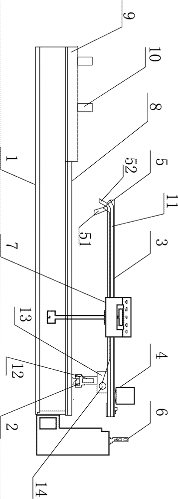
[0026] Such as figure 1 As shown, a liner scraping equipment includes a base 1, a feeding system 2 is installed on the base 1, a lifting mechanism 13 is installed on the feeding system 2, a supporting plate 3 is installed on the lifting mechanism 13, and a supporting plate 3 is installed on the supporting plate 3. There is a hopper 4, and a scraper coating assembly 5 is installed at one end of the supporting plate 3;

[0027] In a further solution, the base 1 is provided with a bracket 9 for supporting the equipment to be scraped, and a pulley 10 is installed on the bracket 9 .

[0028] In a further solution, the base 1 is provided with a guide rail 8 , and the feeding system 2 is installed on the guide rail 8 .

[0029] In a further solution, the feed system 2 is connected with a servo motor 12 .

[0030] In a further solution, the lifting mechanism 13 is also connected with a motor.

[0031] In a further solution, the master mold 51 is connected with the cylinder 14 .

...

Embodiment 2

[0035] The method for scraping the lining of the engine by using the above-mentioned equipment comprises the following steps:

[0036] 1) Install the engine on the pulley 10, adjust its installation height and ensure horizontal installation, and then adjust the height of the supporting plate 3 through the lifting mechanism, so that the part of the engine to be scraped is in contact with the master model 51, and then the scraped Slurry is added in the hopper 4;

[0037] 2) Control the engine to rotate on the pulley 10, the slurry in the hopper 4 reaches the scraper 52 through the screw extrusion device, and the slurry is scraped onto the engine through the scraper 52, and the thickness and trajectory of the scraper are based on the model The position and trajectory of 51 are determined. During the scraping process, the feed system 2 and the lifting mechanism 13 drive the pallet 3, the former 51 and the scraper 52 to move;

[0038] Through the rotation of the engine itself and ...


PUM


Abstract

The invention discloses a liner scraping coating equipment and a scraping coating method thereof. The equipment includes a base, a feeding system is installed on the base, a lifting mechanism is installed on the feeding system, a supporting plate is installed on the lifting mechanism, and a A hopper and a screw extrusion device are installed, and a scraper assembly is installed at one end of the supporting plate; the scraper assembly includes a master and a scraper, and one end of the screw extrusion device is connected to the hopper, and the other end is connected to the scraper. When scraping, first install the engine on the pulley, then adjust the height of the supporting plate so that the part of the engine to be scraped matches the master model, and add the slurry into the hopper; control the engine to rotate on the pulley, and the slurry passes through The screw extrusion device reaches the scraper, and the slurry is scraped onto the engine through the scraper. The invention solves the quality problem that the local thickness of the lining is out of control and improves the production efficiency by controlling the uniform rotation of the engine to be scraped, the accurate positioning of the feeding system, the lifting mechanism and the master, and the accurate feeding of the screw extrusion device.

Description

technical field [0001] The invention belongs to the technical field of engine liner manufacturing, and in particular relates to a liner scraping coating device and a scraping coating method thereof. Background technique [0002] The liner is one of the structural components in the combustion chamber of the solid rocket motor. It is located between the thermal insulation layer and the propellant grain, with a thickness between 0.5mm and 2.0mm. It mainly plays the role of bonding the thermal insulation layer and the propellant. The liner is a polyurethane polymer material, which is a colloidal material with fluidity before curing, and becomes an elastomer material after curing. The forming process of the liner includes the steps of preparing slurry, coating on the surface of the heat insulating layer, pre-curing before charging and curing after charging. The coating process of the lining layer is currently commonly used centrifugal process, manual scraping and high-pressure s...

Claims


Application Information

Patent Timeline
Patent Type & Authority Patents(China)
IPC IPC(8): B05C11/02
Inventor 崔瑞禧柯明朱稼麟陈永钊刘美珍王利明王菲韩寅曾庆江刘敏宋艳朋刘松华刘文辉
Owner HUBEI SANJIANG AEROSPACE JIANGHE CHEM TECH
Learn More