
A mechanical bimetal composite pipe end sealing welding method

A bimetallic composite pipe, mechanical technology, applied in metal processing equipment, workpiece edge parts, manufacturing tools, etc., can solve problems such as welding defects, gas return, affecting the quality of welds, and achieve uniform form and qualified sealing and welding. High rate and the effect of improving the quality of sealing and welding

Active Publication Date: 2017-05-24
XIAN SUNWARD AEROSPACE MATERIAL CO LTD
View PDF5 Cites 0 Cited by
  • Summary
  • Abstract
  • Description
  • Claims
  • Application Information

AI Technical Summary

Problems solved by technology

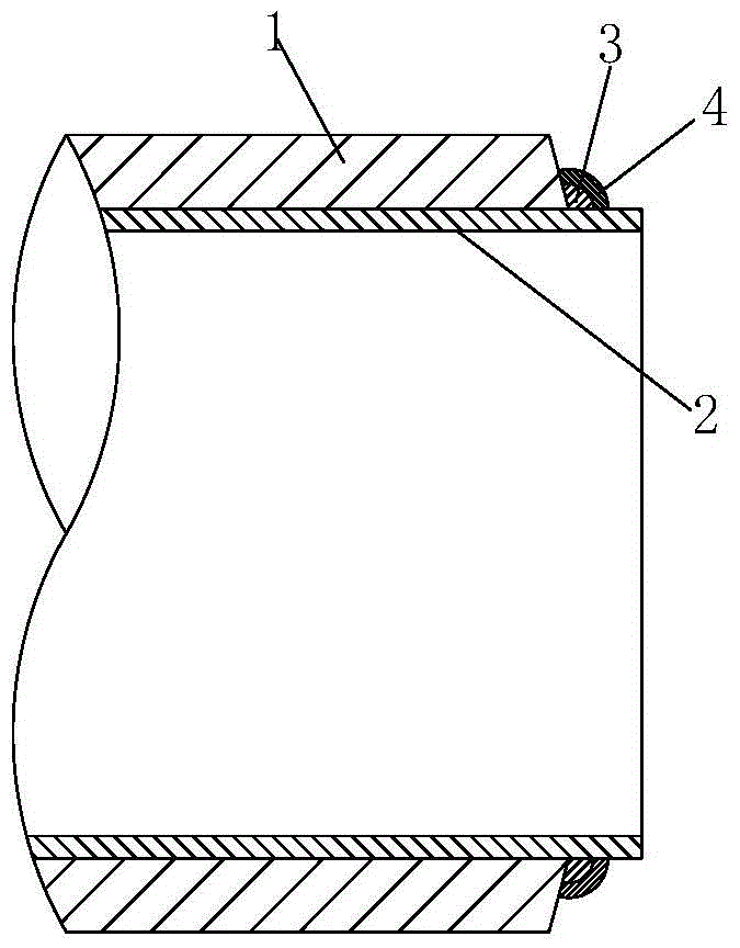
[0003] 1. Pollutants, water and water vapor will enter the gap between the base pipe 1 and the liner pipe 2 from the pipe end, affecting the welding quality of the composite pipe;
[0004] 2. The pipe end of the liner 2 is easily deformed during the transportation process, and the requirements for the ellipticity of the pipe end of the pipe butt welding cannot be guaranteed
[0006] 1. Due to the ellipticity of the pipe, the interface between the base pipe 1 and the liner 2 often has the problem that the base pipe 1 residue that has not been turned completely or the outer surface of the liner 2 is scratched by the tool when the groove is processed;
[0007] 2. The existing sealing welding groove is a unilateral V-shaped groove, but the poor fluidity of the molten pool at the root during sealing welding will cause unmelted defects at the root, which seriously affects the quality of the weld, and because the base pipe 1 and the liner pipe 2 The penetration depth at the root of the gap is very shallow. In the subsequent butt welding process, due to the pre-weld grinding and high welding heat input, it is very easy to cause the sealing layer to be penetrated and return gas, resulting in serious welding defects.

Method used


Image

  • A mechanical bimetal composite pipe end sealing welding method
  • A mechanical bimetal composite pipe end sealing welding method
  • A mechanical bimetal composite pipe end sealing welding method

Examples


Embodiment Construction

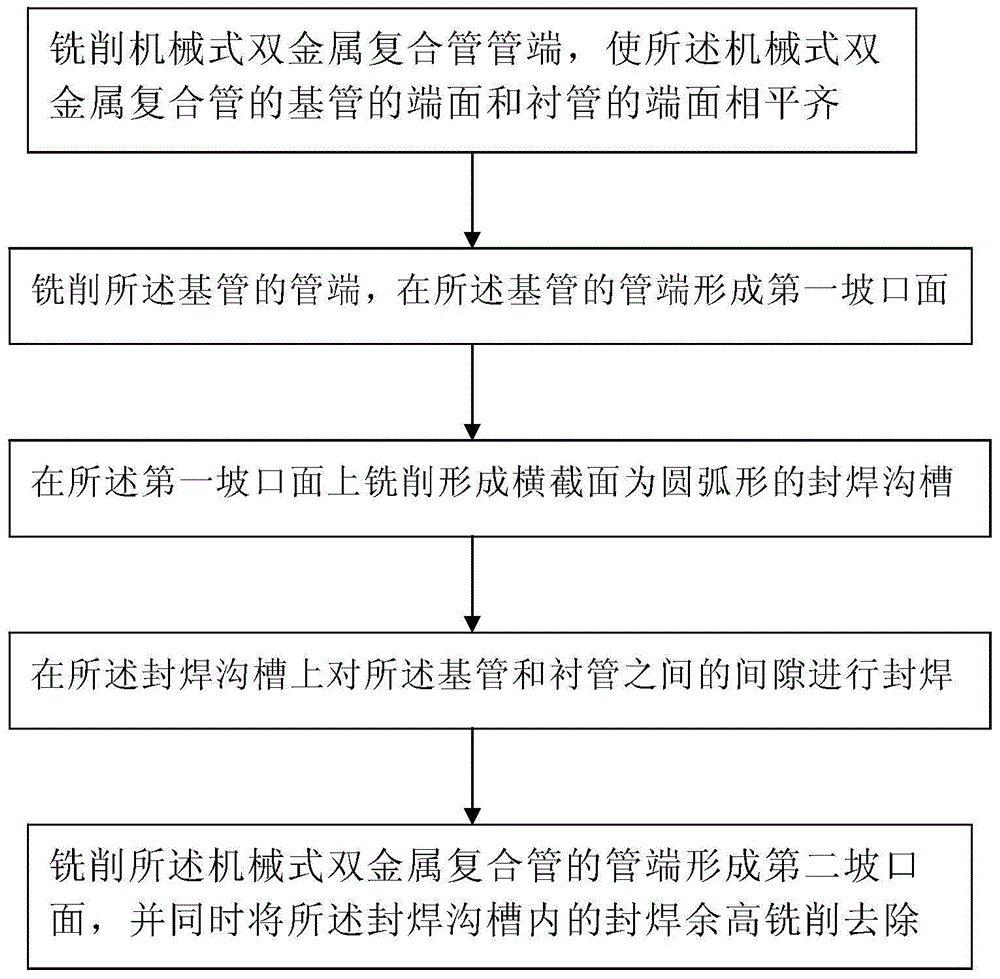
[0052] like Figure 2 to Figure 8 A mechanical bimetal composite pipe end sealing welding method shown comprises the following steps:

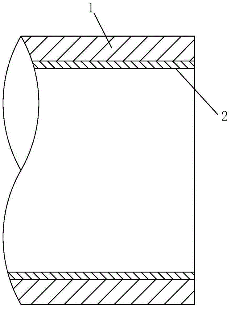
[0053] Step 1, milling the end of the mechanical bimetallic composite pipe, so that the end face of the base pipe 1 of the mechanical bimetallic composite pipe is flush with the end surface of the liner 2, wherein the base pipe of the mechanical bimetallic composite pipe The end face of the pipe 1 and the end face of the liner 2 are flush, that is, the end face of the base pipe 1 and the end face of the liner 2 are both perpendicular to the central axis of the mechanical bimetal composite pipe;

[0054] combine image 3 , in this embodiment, in step 1, the end face of the base pipe 1 and the end face of the liner 2 of the mechanical bimetallic composite pipe are milled flush with the first end face turning tool with an entering angle of 90°, so that The first end turning tool is installed on the boring machine. This method uses the first end...


PUM


Abstract

The invention discloses a method for sealing weld of the pipe end of a mechanical bimetal composite pipe. The method comprises the following steps: the first step of milling the pipe end of the mechanical bimetal composite pipe, so that the end face of a mechanical bimetal composite pipe base pipe is level with the end face of a liner pipe; the second step of milling the pipe end of the base pipe, and forming a first groove face at the pipe end of the base pipe; the third step of milling the first groove face to form a sealing weld groove with the cross section in an arc shape; the fourth step of performing sealing weld on gaps between the base pipe and the liner pipe on the sealing weld groove; the fifth step of milling the pipe end of the mechanical bimetal composite pipe to form a second groove face, and milling and removing sealing weld excess weld metal in the sealing weld groove. According to the sealing weld method, molten pool flowing in bottoming welding is effectively restrained by forming the sealing weld groove, the shortcoming that the root of a weld joint is not molten is overcome fundamentally, and the sealing weld quality is improved. Due to the sealing weld groove, the thickness of the sealing weld joint is increased, groove processing is performed already after the sealing weld is finished, and accordingly the on-site butt welding efficiency and quality are improved.

Description

technical field [0001] The invention belongs to the technical field of welding groove processing, and in particular relates to a mechanical bimetal composite pipe end sealing welding method. Background technique [0002] like figure 1 As shown, the existing mechanical composite pipe is composed of a base pipe 1 and a liner 2 sleeved inside the base pipe 1. The base pipe 1 mainly acts as a pressure bearing, and its material is generally medium-high carbon steel; the liner 2 mainly It plays a role of corrosion resistance, and its material is generally stainless steel. The mechanical bimetal composite pipe is mechanically bonded through the interference fit between the base pipe 1 and the liner 2, so there is a certain gap between the base pipe 1 and the liner 2 interface, and the gap between the base pipe 1 and the liner 2 The presence of will cause the following problems: [0003] 1. Pollutants, water and water vapor will enter the gap between the base pipe 1 and the liner...

Claims


Application Information

Patent Timeline
Patent Type & Authority Patents(China)
IPC IPC(8): B23P15/00B23K33/00
CPCB23K33/00B23P15/00
Inventor 王斌朱加强王剑傅海姜义郭霖梁国栋魏帆孙兵赵欣王思恩
Owner XIAN SUNWARD AEROSPACE MATERIAL CO LTD
Learn More