
Plate surface grinding equipment

A plate and equipment technology, applied in the field of plate surface grinding equipment, can solve the problems of long processing cycle and delay in production process, and achieve the effect of high film removal efficiency, simple and reasonable structure design, and high degree of automation

Inactive Publication Date: 2015-12-09
天津市帝标建材有限公司
View PDF8 Cites 33 Cited by
  • Summary
  • Abstract
  • Description
  • Claims
  • Application Information

AI Technical Summary

Problems solved by technology

However, when the oxide film on the surface of the raw material plate is relatively thick, the treatment period of the above-mentioned chemical method is relatively long, which delays the production process and requires a certain mechanical film removal method as an auxiliary

Method used


Image

  • Plate surface grinding equipment
  • Plate surface grinding equipment

Examples


Embodiment Construction

[0012] In order to further understand the content of the invention, characteristics and effects of the present invention, the following examples are described in detail as follows:

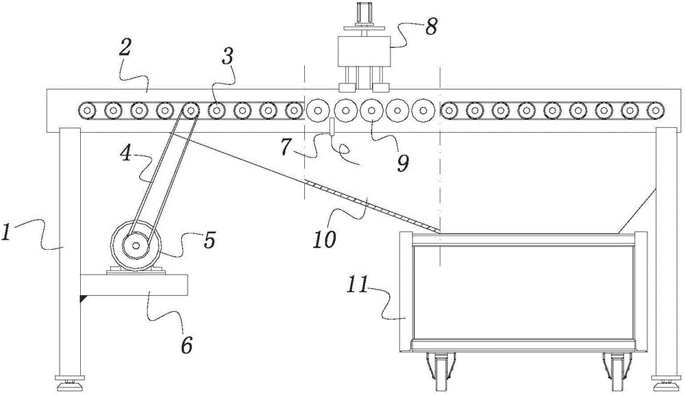
[0013] See figure 1 , the present invention includes two front and rear side plates 2 supported by a plurality of columns 1 and oppositely arranged, between the two side plates 2, a plurality of idler rollers 9 of equal height are erected and installed along the length direction, and each idler roller The end of the same side of the mandrel 9 is provided with a driven sprocket 3, and a chain 4 is sleeved on each driven sprocket 3, and a crossbeam 6 is fixedly connected to the column 1, and a deceleration gear is installed on the crossbeam 6. Machine 5, the driving sprocket on its output shaft adopts chain 4 to connect transmission with wherein a driven sprocket 3. Driven by the reducer 5, each idler roller 9 rotates synchronously and slowly.

[0014] A grinding mechanism 8 is installed between t...


PUM


Abstract

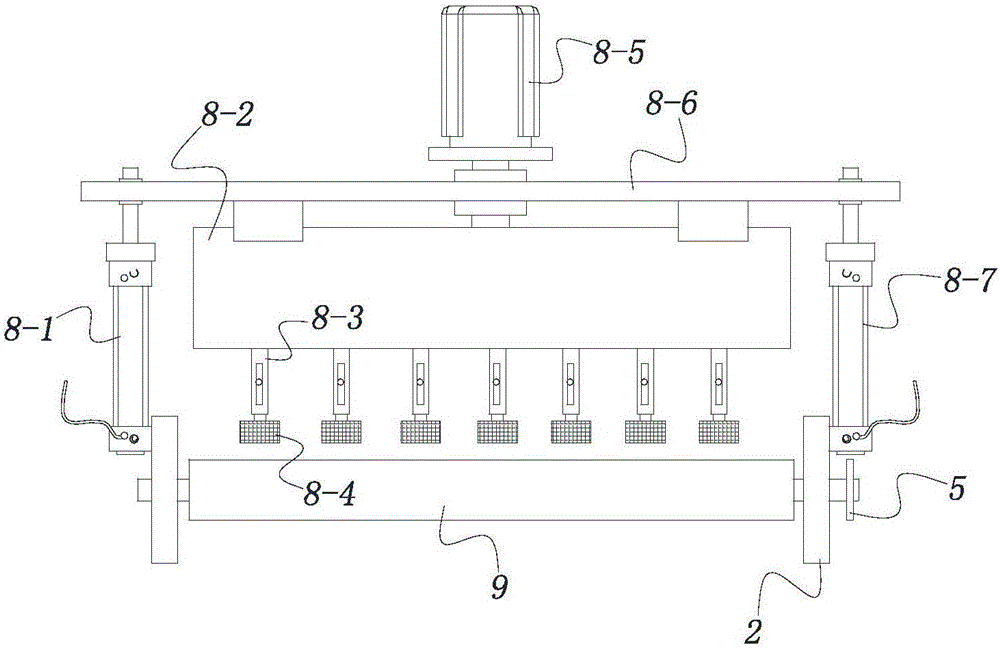
The invention relates to plate surface grinding equipment. The plate surface grinding equipment is composed of a front lateral plate and a rear lateral plate which are supported by vertical pillars and arranged oppositely. A plurality of carrier rollers at the same height are erected between the two lateral plates in the length direction. Driven sprockets are arranged at the ends, on the same side, of all carrier roller core shafts. A cross beam is fixedly connected with one of the vertical pillars, and a speed reducer used for driving the driven sprockets to rotate synchronously is installed on the cross beam. A grinding mechanism is installed between the middles of the two lateral plates and comprises a first hydraulic cylinder and a second hydraulic cylinder vertically and fixedly installed in the middles of the two lateral plates respectively. A lifting plate is erected between the upper ends of pistons of the two hydraulic cylinders, a shaft sleeve is arranged in the middle of the lifting plate, a single-input and multi-output gearbox is fixedly installed at the bottom of the lifting plate, and an input shaft of the gearbox is located in the shaft sleeve. The plate surface grinding equipment further comprises a motor used for driving the input shaft, output shafts fall into a front row and a rear row, the intervals between the output shafts in each row are the same, the output shafts of the two rows are arranged in a staggered mode, and grinding heads are installed at the bottoms of all the output shafts.

Description

technical field [0001] The invention belongs to the technical field of plate processing equipment, in particular to a plate surface grinding equipment. Background technique [0002] In the processing procedure of aluminum veneer products, since the surface of the raw material plate usually has an oxide film and the oxide film will affect the subsequent processes such as chromization process and spraying process, it is necessary to polish the surface of the plate before putting into the specific processing procedure , to remove the above oxide film. The method of removing the oxide film in the prior art is generally a chemical method, that is, immersing the raw plate in an acidic or alkaline solution. The oxide film on the surface is removed by chemical reaction. However, when the oxide film on the surface of the raw material plate is relatively thick, the treatment period of the above-mentioned chemical method is relatively long, which delays the production process and req...

Claims


Application Information

Patent Timeline
Patent Type & Authority Applications(China)
IPC IPC(8): B24B7/10B24B27/033B24B47/12B24B55/06B24B51/00
CPCB24B7/10B24B27/033B24B47/12B24B51/00B24B55/06
Inventor 孙波
Owner 天津市帝标建材有限公司
Learn More