Auxiliary bonding device of winder yarn connector and application method for auxiliary bonding device

A technology for bonding device and spinning yarn, applied in the field of weaving processing, can solve the problems of incomplete cohesion, weak wear resistance of yarn joints, easy end breakage, etc., so as to improve production efficiency, improve yarn wear resistance, Strong joint effect

Active Publication Date: 2015-12-09
GUANGDONG ESQUEL TEXTILES CO LTD +3
View PDF7 Cites 3 Cited by
  • Summary
  • Abstract
  • Description
  • Claims
  • Application Information

AI Technical Summary

Problems solved by technology

[0002] The winding process is indispensable in the spinning process. The winding machine can remove the defects on the yarn and then re-splicing, and can turn the cop yarn into a large-capacity bobbin through the splicing method, which can improve the efficiency of subsequent processing. Production efficiency; the wear resistance of the yarn joint is weaker than that of the main body of the yarn, because the two yarns are not completely entangled after untwisting and retwisting, especially the fibers at the end of the joint are entangled on the surface of the yarn jointed with it, and are not effectively affected. The end fiber is not fully involved in the yarn body due to gripping, and it is easy to break when weaving

Method used


Image

  • Auxiliary bonding device of winder yarn connector and application method for auxiliary bonding device
  • Auxiliary bonding device of winder yarn connector and application method for auxiliary bonding device
  • Auxiliary bonding device of winder yarn connector and application method for auxiliary bonding device

Examples


Embodiment 1

[0032] This embodiment provides an auxiliary bonding device for yarn joints of a winder.

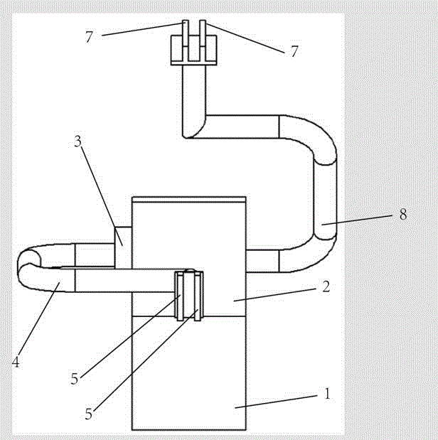
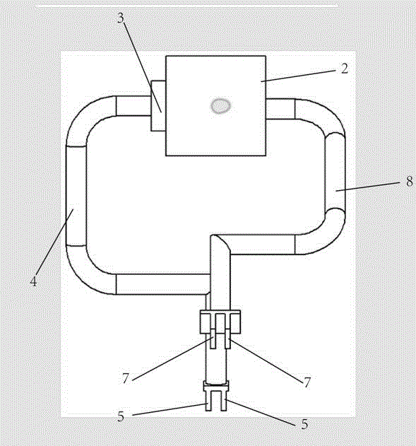
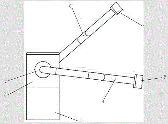
[0033] An auxiliary bonding device for yarn joints of a winding machine, see Figure 1-Figure 4 As shown, it includes a storage part 2, a signal receiving part 3, a material channel 4, a printing plate 5, a heat treatment part, a driving part and a transmission part, the signal receiving part 3 is installed in the storage part 2, and the transmission Components are connected to the storage part 2 for moving the storage part 2; the storage part 2 is supported by metal, plastic or polymer material, and the length of the storage part 2 is 100-500mm and the width is 50-200mm, the height is level with the splicer position of the winding machine. The function of the signal receiving part 3 is to receive the knotting signal of the splicer.

[0034] The length of the printing plate 5 is 30-80mm, and the width is 2-10mm. The printing plate 5 is connected to the storage part 2 through the materi...

Embodiment 2

[0043] This embodiment provides a method for using an auxiliary bonding device for yarn joints of a winder.

[0044] A method for using an auxiliary bonding device for yarn joints of a winding machine, comprising the following steps:

[0045] The transmission part makes the winding machine yarn splicing auxiliary bonding device (mobile base 1) move around the front of the winding machine through the transmission belt, and the mobile signal receiving part 3 on the storage part 2 receives the broken spindle signal of the winding machine, The transmission part moves the yarn joint auxiliary bonding device (moving base 1) of the winding machine to the yarn joint 91 of the spindle splicer;

[0046] The first driving element drives the material channel 4 to rotate around the material storage part 2 to the yarn joint, and squeezes the material channel 4 so that the glue in the material storage part 2 passes through the material channel 4 and the printing plate 5. The material outlet...

Embodiment 3

[0052] This embodiment provides a method for using an auxiliary bonding device for yarn joints of a winder.

[0053] A method for using an auxiliary bonding device for yarn joints of a winding machine, comprising the following steps:

[0054] The transmission part makes the winding machine yarn splicing auxiliary bonding device (mobile base 1) move around the front of the winding machine through the transmission belt, and the mobile signal receiving part 3 on the storage part 2 receives the broken spindle signal of the winding machine, The transmission part moves the yarn joint auxiliary bonding device (moving base 1) of the winding machine to the yarn joint 91 of the spindle splicer;

[0055] The first driving element drives the material channel 4 to rotate around the material storage part 2 to the yarn joint, and squeezes the material channel 4 so that the glue in the material storage part 2 passes through the material channel 4 and the printing plate 5. The discharge port ...


PUM


Abstract

The invention discloses an auxiliary bonding device of a winder yarn connector and an application method for the auxiliary bonding device. The auxiliary bonding device of the winder yarn connector comprises a storage part, a signal receiving component, a material channel, printing plates, thermal processing components, a drive component and a conveying component. The signal receiving component is installed on the storage part. The conveying component is connected to the storage part and used for moving the storage part. The printing plates are provided with discharging ports. At least two printing plates are arranged. An interval is reserved between the two printing plates, and the discharging ports of the printing plates are opposite. One end of the material channel is communicated with the storage part, and the other end of the material channel is communicated with the discharging ports of the printing plates. The drive component is connected to the printing plates and drives the printing plates to move. The thermal processing components are installed on the storage part, and the drive component is connected to the thermal processing components and drives the thermal processing components to move. According to the auxiliary bonding device of the winder yarn connector, woven broken heads are reduced, the efficiency of a weaving machine is improved, and warp stopping or weft stopping caused by poor abrasion resistance of the yarn connector is avoided.

Description

technical field [0001] The invention relates to the field of weaving processing, in particular to an auxiliary bonding device for yarn joints of a winding machine and a method for using the same. Background technique [0002] The winding process is essential in the spinning process. The winding machine can remove the defects on the yarn and then re-splicing, and can turn the bobbin into a large-capacity bobbin through splicing, which can improve the efficiency of subsequent processing. Production efficiency; the wear resistance of the yarn joint is weaker than that of the main body of the yarn, because the two yarns are not completely entangled after untwisting and retwisting, especially the fibers at the end of the joint are entangled on the surface of the yarn jointed with it, and are not effectively affected. As a result, the end fibers are not fully involved in the yarn body due to holding, and it is easy to break when weaving. [0003] In the production and processing ...

Claims


Application Information

Patent Timeline
Patent Type & Authority Applications(China)
IPC IPC(8): B65H69/02B65H69/04
Inventor 何小东颜丹丹宋均燕贾文杰刘霞张玉高
Owner GUANGDONG ESQUEL TEXTILES CO LTD
Why Eureka
Try Eureka