Sectional pressurized organic waste gasifier

An organic waste and gasifier technology, applied in the manufacture of combustible gas, petroleum industry, etc., can solve the problems of low gas quality, incomplete redox reaction, unsatisfactory gasification effect, etc. Secondary pollution, the effect of improving gas quality

Inactive Publication Date: 2017-10-03
曾中伟 +2
View PDF6 Cites 0 Cited by
  • Summary
  • Abstract
  • Description
  • Claims
  • Application Information

AI Technical Summary

Problems solved by technology

[0003] In order to solve the deficiencies of the above-mentioned problems in the prior art, the present invention provides a staged pressurized organic waste gasifier, which solves the problem of unsatisfactory gasification effect, pyrolysis of waste organic matter in the furnace, and poor oxidation-reduction reaction in the prior art. Thorough, low gas quality and other issues

Method used


Image

  • Sectional pressurized organic waste gasifier

Examples


Embodiment 1

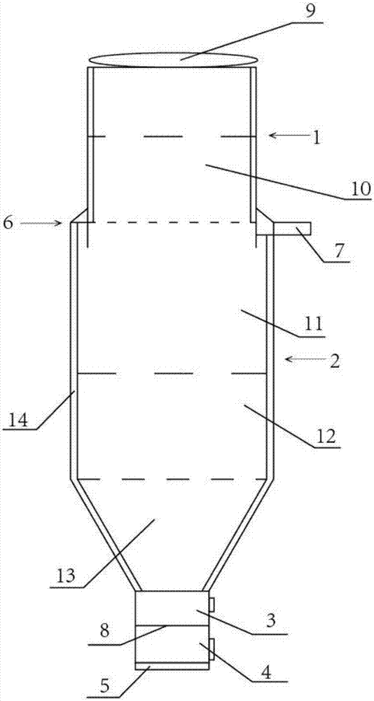
[0017] Embodiment 1 is a preferred embodiment of the present invention, as attached figure 1 Shown: a segmented pressurized organic waste gasification furnace, including an upper furnace body 1, a lower furnace body 1, an ignition area 3, an air supply area 4 and an ash outlet 5 which are sequentially combined and connected, and the upper and lower furnace bodies are two concentric cylinders. The total height of the furnace body is 4000 mm, the height of the lower furnace body 2 is 2000 mm, the diameter is 1500 mm, the height of the upper furnace body 1 is also 2000 mm, and the diameter is reduced to 80% of the diameter of the lower furnace body 2 1 diameter is 1200mm. The bottom of upper furnace body 1 stretches into lower furnace body 2 top slightly, and about 20 centimeters is deep, with the steel plate of same material with furnace body as a whole with certain inclination welding upper and lower two furnace bodies. The difference in diameter between the upper furnace bod...

Embodiment 2

[0024] Embodiment 2 is another preferred embodiment of the present invention. In embodiment 2, the diameter of the lower furnace body 2 is 2000 mm, and the diameter of the upper furnace body 1 is 1500 mm. The bottom end of the upper furnace body 1 slightly extends into the lower furnace body 2 top. , about 10 centimeters deep, it is the same as embodiment 1.

[0025] The working principle of the present invention is: in the gasification process of garbage organic matter, due to the narrowing of the upper furnace body 1, the gas in the furnace moves from bottom to top, the gas density in the upper furnace body 1 increases, and the gas in the upper furnace body 1 rises to After the top, under the greater pressure, the rising gas returns quickly, so the density of the middle pyrolysis zone 11 will increase correspondingly, and the pyrolysis rate will also increase accordingly. The reduction zone 12 and oxidation zone 13 in the lower part The speed is also accelerated accordingly,...


PUM


Abstract

The invention discloses a segmented pressurized organic waste gasification furnace, which comprises an upper furnace body, a lower furnace body, an ignition area, an air supply area and an ash outlet which are sequentially combined and connected, and is characterized in that: the upper and lower furnace bodies are Two concentric cylinders, the height of the upper and lower furnace bodies is equal, the diameter of the upper furnace body is 80-85% of the diameter of the lower furnace body; the bottom of the upper furnace body extends into the top of the lower furnace body 10-20 cm deep, and the upper The difference in diameter between the furnace body and the lower furnace body is sealed and welded with a steel plate, which is used as an air intake tank, and one end of the air intake tank is connected to the air intake pipe through an opening; there is an air distribution plate between the ignition area and the air supply area; the upper furnace The top of the body is an opening for putting in garbage, and a top cover is provided on the upper part of the opening. In the present invention, by reducing the size of the upper furnace body, the pressure is increased ingeniously and the speed is increased, thereby improving the gasification effect and the quality of gas production.

Description

technical field [0001] The invention relates to an organic waste gasification furnace, in particular to a segmented pressurized organic waste gasification furnace. Background technique [0002] At present, the more common waste gasifiers are mainly divided into three types: up-suction type, down-suction type and medium-conduction type. The principle is to feed the gasifier from the top of the gasifier, and add a small amount of wood chips and other biomass raw materials to support combustion in the bottom layer of the furnace body. , open the bottom outside the furnace body for ignition, oxygen supply, air supply and ash removal. Combustible gas is generated through four thermochemical reaction processes of oxidation, reduction, pyrolysis and drying, and is discharged through the external pipe of the exhaust port. The difference between the three methods is that the gas inlets are different. The up-suction type takes gas from the upper part of the furnace body, the down-suct...

Claims


Application Information

Patent Timeline
Patent Type & Authority Patents(China)
IPC IPC(8): C10J3/20C10J3/26C10J3/66C10J3/74
Inventor 曾中伟
Owner 曾中伟
Why Eureka
Try Eureka