Burner for pulverized coal gasifier

A technology of gasifier and pulverized coal, which is applied in the field of burners, can solve the problems of inconvenient disassembly and maintenance, high processing and manufacturing costs, and complicated manufacturing processes, so as to avoid burning loss, reduce the contact area and protect the burners Effect

Active Publication Date: 2018-07-06
HARBIN INST OF TECH
View PDF9 Cites 0 Cited by
  • Summary
  • Abstract
  • Description
  • Claims
  • Application Information

AI Technical Summary

Problems solved by technology

[0003] In order to solve the problems of complex manufacturing process, high manufacturing cost, inconvenient disassembly and maintenance, and short service life of the pulverized coal gasifier burner in the prior art, the present invention further provides a pulverized coal gasifier burner

Method used


Image

  • Burner for pulverized coal gasifier
  • Burner for pulverized coal gasifier

Examples


specific Embodiment approach 1

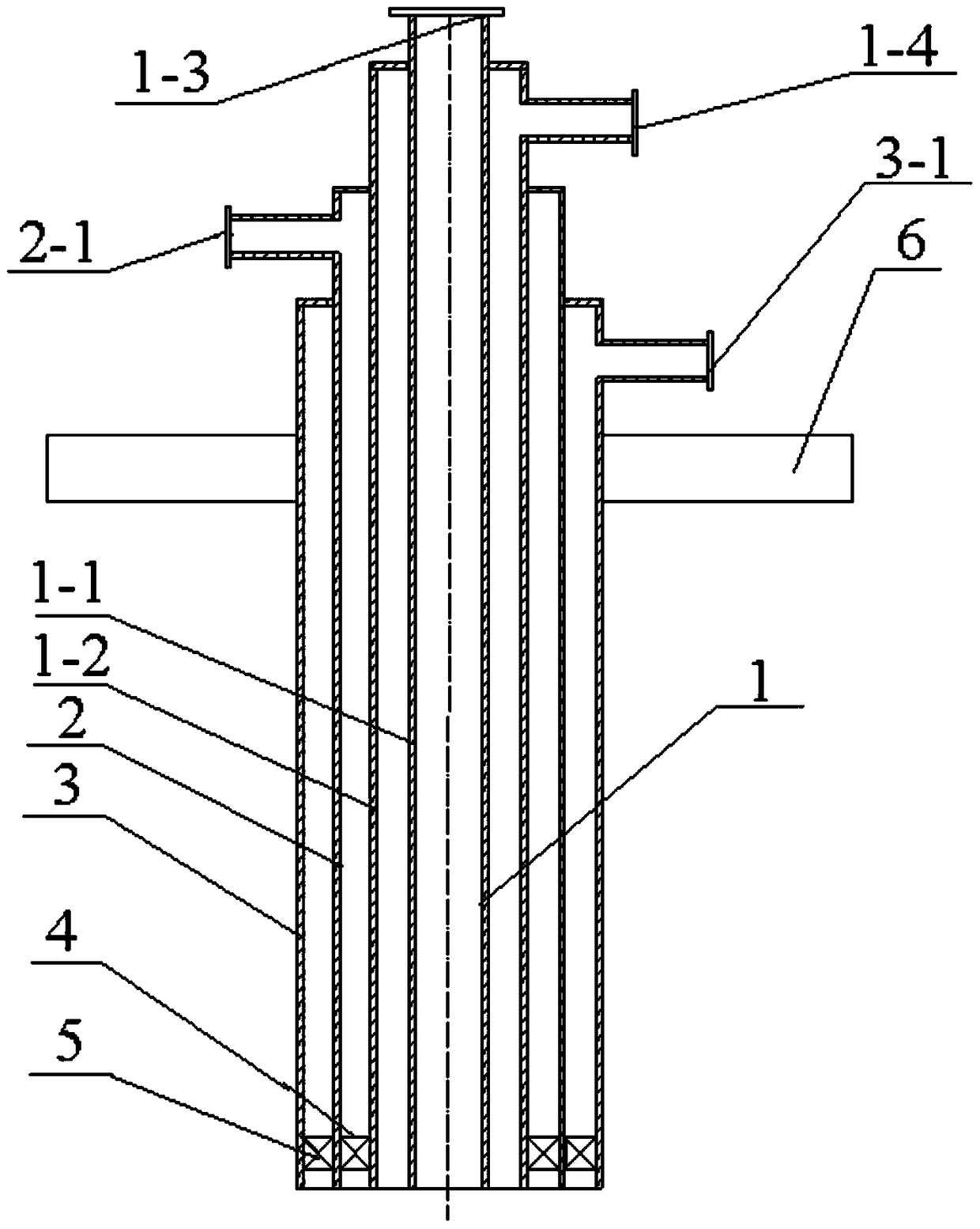
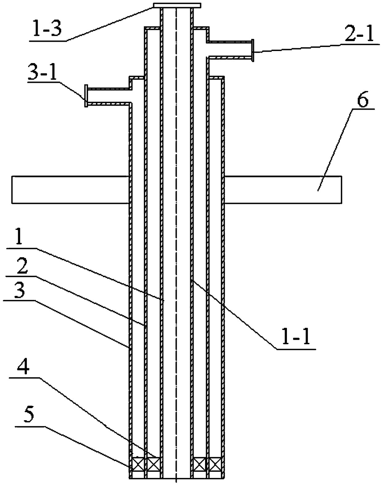
[0014] Specific implementation mode one: combine Figure 1-Figure 2 Description of this embodiment, a pulverized coal gasifier burner, which includes at least one layer of protective gas pipeline 1, gasification agent pipeline 2, pulverized coal pipeline 3, first swirl blade 4, second swirl blade 5 and Flange 6; the gasification agent pipeline 2 is set on the outside of at least one layer of protective gas pipeline 1, the pulverized coal pipeline 3 is set on the outside of the gasification agent pipeline 2, and the flange 6 is set on the outer wall of the pulverized coal pipeline 3, The first swirl blade 4 is arranged between the outer wall of at least one layer of shielding gas pipeline 1 and the inner wall of gasification agent pipeline 2, and the second swirl blade 5 is arranged between the outer wall of gasification agent pipeline 2 and the pulverized coal pipeline 3 between the inner sidewalls, and the first swirl vane 4 and the second swirl vane 5 are set close to the bo...

specific Embodiment approach 2

[0016] Specific implementation mode two: combination figure 2 Describe this embodiment, a pulverized coal gasifier burner of this embodiment, the protective gas pipeline of the at least one layer of protective gas pipeline 1 is the first protective gas pipeline 1-1 of one layer, other structures and specific implementation Method 1 is the same.

specific Embodiment approach 3

[0017] Specific implementation mode three: combination figure 1 Describe this embodiment, a pulverized coal gasifier burner of this embodiment, the protective gas pipeline of the at least one layer of protective gas pipeline 1 is two layers of the first protective gas pipeline 1-1 and the second protective gas pipeline 1-2, the second protective gas pipeline 1-2 is sleeved on the first protective gas pipeline 1-1, and the top of the second protective gas pipeline 1-2 is sealed with the outer wall of the first protective gas pipeline 1-1, The top of the first shielding gas pipeline 1-1 is processed with a first shielding gas inlet 1-3, and the side wall of the second shielding gas pipeline 1-2 is processed with a second shielding gas inlet 1-4 near the top. Other structures and specific embodiments One is the same.

[0018] Specific implementation mode four: combination figure 1 Describe this embodiment, a pulverized coal gasifier burner of this embodiment, the first protecti...


PUM


Abstract

A burner for a pulverized coal gasifier. The present invention relates to a burner. The present invention solves the problem of complex manufacturing process, high manufacturing cost, inconvenient disassembly and maintenance, and The problem of short service life, which includes at least one layer of shielding gas pipeline, gasification agent pipeline, pulverized coal pipeline, first swirl blade, second swirl blade and flange; gasification agent pipeline is sleeved on at least one layer of protection Outside the gas pipeline, the pulverized coal pipeline is sleeved outside the gasification agent pipeline, the flange is sleeved on the outer wall of the pulverized coal pipeline, and the first swirl vane is set on at least one layer of the outer wall of the protective gas pipeline and the inner side of the gasification agent pipeline Between the walls, the second swirl vane is set between the outer wall of the gasification agent pipeline and the inner wall of the pulverized coal pipeline, and the top of the pulverized coal pipeline is provided with a pulverized coal airflow inlet, and the top of the gasification agent pipeline is provided with a gas flow inlet. The inlet of the protective gas is provided at the top of at least one layer of the protective gas pipeline. The invention is used in a coal gasification device.

Description

technical field [0001] The invention relates to a burner, in particular to a burner for a pulverized coal gasification furnace. Background technique [0002] Coal is an important energy source, but for a long time, the use of coal has been accompanied by serious environmental pollution problems. In recent years, people have paid more and more attention to clean coal technology aimed at reducing pollution emissions and improving utilization efficiency; and coal gasification technology is an efficient and clean clean coal technology. The burner is the key component of the coal gasification device. The burner is in a high-temperature environment for a long time, and it is very easy to burn out. Once the burner is burned out, the gasification device must be shut down, causing huge economic losses to the enterprise. Chinese Invention Patent Application Publication No. CN1710333A discloses a swirl burner, in which three-stage water-cooled jackets are arranged coaxially in sequen...

Claims


Application Information

Patent Timeline
Patent Type & Authority Patents(China)
IPC IPC(8): C10J3/50
Inventor 曾令艳陈智超李争起王浩鹏刘晓英蒋炳坤朱群益
Owner HARBIN INST OF TECH
Why Eureka
Try Eureka