Anchorage Structure of Steel-Concrete Composite Cable Beams for Cable-Stayed Bridges

A cable-stayed bridge steel and cable-stayed bridge technology, applied in cable-stayed bridges, bridges, bridge parts, etc., can solve problems such as complex local structures, and achieve excellent mechanical performance, improved fatigue performance, and good use effects.

Inactive Publication Date: 2017-06-20
CHANGAN UNIV
View PDF7 Cites 0 Cited by
  • Summary
  • Abstract
  • Description
  • Claims
  • Application Information

AI Technical Summary

Problems solved by technology

The cable force is transmitted to the main girder through the weld seam of the anchor tie plate. In order to make the cable force evenly transmitted to the main beam, more stiffeners are set at the joint between the anchor tie plate and the main beam, and the local structure is relatively complicated.

Method used


Image

  • Anchorage Structure of Steel-Concrete Composite Cable Beams for Cable-Stayed Bridges
  • Anchorage Structure of Steel-Concrete Composite Cable Beams for Cable-Stayed Bridges
  • Anchorage Structure of Steel-Concrete Composite Cable Beams for Cable-Stayed Bridges

Examples


Embodiment 1

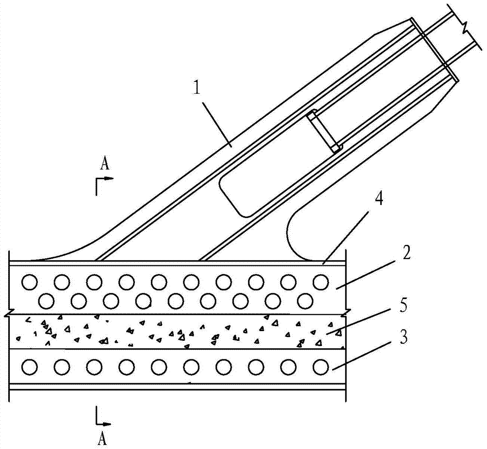
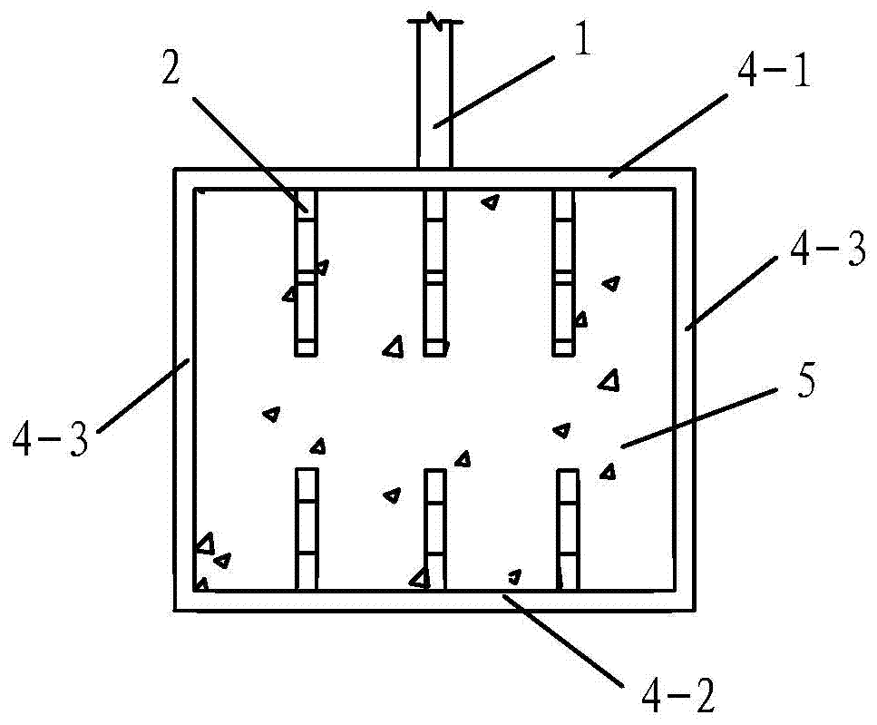
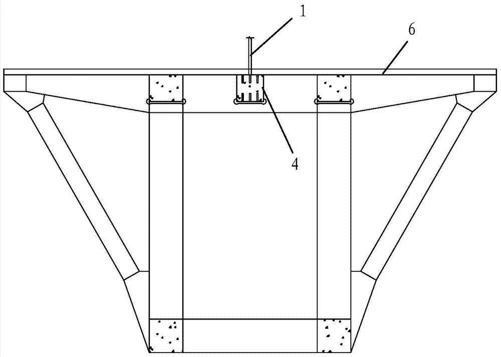
[0033] Such as figure 1 , figure 2 As shown, the present invention includes a rectangular steel pipe 4, a stiffener assembly arranged in the rectangular steel pipe 4, a concrete structure 5 formed by pouring concrete filled in the rectangular steel pipe 4, and a concrete structure 5 arranged on the rectangular steel pipe 4 and applied to the cable-stayed bridge. Anchor plate 1 fixed with stay cables, the stiffener assembly is poured in the concrete structure 5, the rectangular steel pipe 4, the stiffener assembly and the concrete structure 5 form a stiffened steel pipe concrete member, and the stiffened The steel tube concrete member is fastened and fixed on the main girder of the cable-stayed bridge. The rectangular steel pipe 4 is arranged horizontally and along the longitudinal direction of the bridge. The rectangular steel pipe 4 is connected to the top board 4-1 and the bottom board 4-2 directly below the top board 4-1 by the top board 4-1, and two The side plates 4-3 ...

Embodiment 2

[0049] In this example, if Figure 5 As shown, the difference from Embodiment 1 is that the upper opening stiffeners 2 and the lower opening stiffeners 3 are arranged in a staggered manner.

[0050] In this embodiment, the number of the upper opening stiffeners 2 is three, and the number of the lower opening stiffeners 3 is two. During actual construction, the numbers of the upper opening stiffeners 2 and the lower opening stiffeners 3 can be adjusted accordingly according to specific needs.

[0051] In this embodiment, the structures and connections of other parts are the same as those in Embodiment 1.


PUM


Abstract

The invention discloses a cable-stayed bridge steel-mixed composite cable girder anchorage structure, which comprises a rectangular steel pipe, a stiffener assembly arranged in the rectangular steel pipe, a concrete structure formed by pouring concrete filled in the rectangular steel pipe, and a rectangular steel pipe arranged in the rectangular steel pipe. The anchor plate on the top, rectangular steel pipes, stiffener components and concrete structure constitute the stiffened CFST members; the rectangular steel pipes are arranged along the longitudinal bridge direction, and the rectangular steel pipes are spliced ​​by the top plate, bottom plate and two side plates, and the stiffener components include multiple An upper opening stiffener fixed on the bottom of the top plate from left to right and a plurality of lower opening stiffeners fixed on the top of the bottom plate from left to right. The invention is simple in structure, reasonable in design, convenient in construction, and good in use effect. It combines the rectangular steel tube concrete structure with opening stiffeners and the traditional anchor plate, under the premise of ensuring reasonable force and reliable force transmission. The pressure-bearing requirement of the horizontal force component of the stay cable is also conducive to improving the fatigue performance of the anchorage part of the cable beam.

Description

technical field [0001] The invention belongs to the technical field of bridge engineering, in particular to a steel-concrete composite cable girder anchorage structure of a cable-stayed bridge. Background technique [0002] The cable-beam anchorage system is an important component of force transmission in cable-stayed bridges, and its reasonable force and reliable force transmission are the key to structural design. The more common cable-girder anchorage systems in steel box-girder cable-stayed bridges include anchor-box connections, ear-plate connections, anchor-tube connections, and anchor-stay-plate connections. Among them, the anchor-stayed connection adopts the anchor-stayed plate as the main load-bearing structure, and the anchor-stayed plate is terminated with a stay cable, and the lower end is connected with a steel girder. The cable force is transmitted to the main girder through the weld seam of the anchor tie plate. In order to transmit the cable force to the mai...

Claims


Application Information

Patent Timeline
Patent Type & Authority Patents(China)
IPC IPC(8): E01D19/14E01D11/04
Inventor 刘永健熊治华张凯姜磊王成坤李鸿升
Owner CHANGAN UNIV
Why Eureka
Try Eureka