Radial rim sealing structure with damping holes and flow guide blades

A technology of guide vanes and sealing structure, applied in the direction of preventing leakage, engine components, machines/engines, etc., can solve problems such as limited effect, and achieve the effects of improving sealing performance, improving economy, and improving heat transfer stability.

Active Publication Date: 2015-12-09
XI AN JIAOTONG UNIV
View PDF5 Cites 11 Cited by
  • Summary
  • Abstract
  • Description
  • Claims
  • Application Information

AI Technical Summary

Problems solved by technology

Although the radial sealing structure can reduce the degree of gas intrusion to a certain extent, the effect is limited. Therefore, the new radial rim seal that can more effecti...

Method used


Image

  • Radial rim sealing structure with damping holes and flow guide blades
  • Radial rim sealing structure with damping holes and flow guide blades
  • Radial rim sealing structure with damping holes and flow guide blades

Examples


Embodiment Construction

[0033] The present invention will be further described in detail below in conjunction with the accompanying drawings and technical principles.

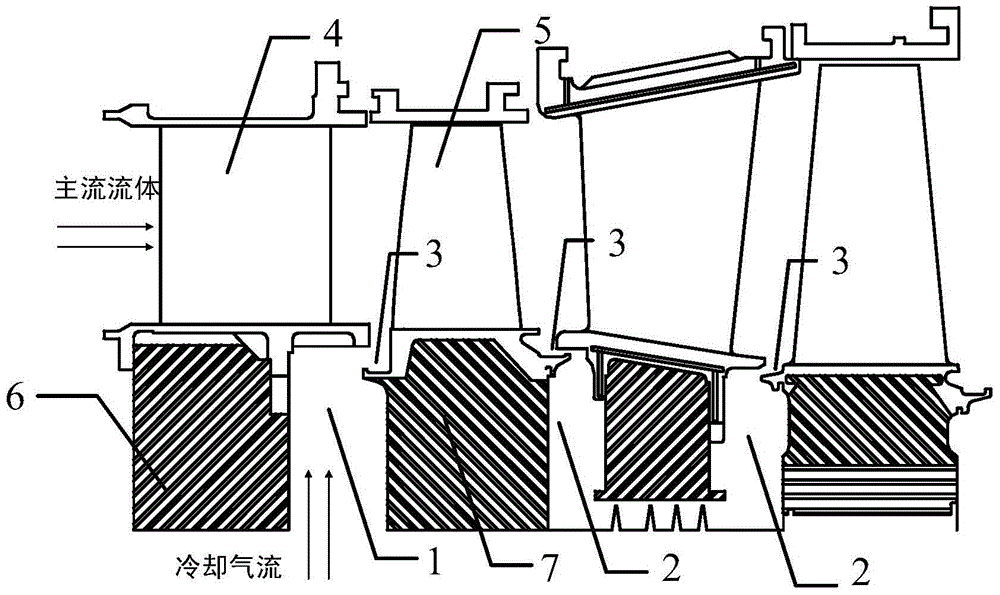
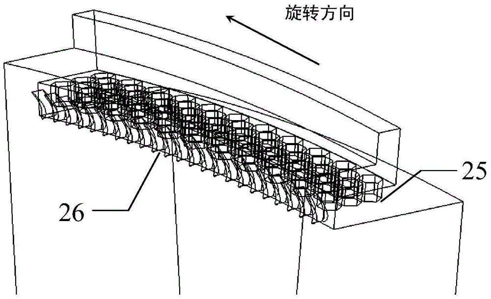
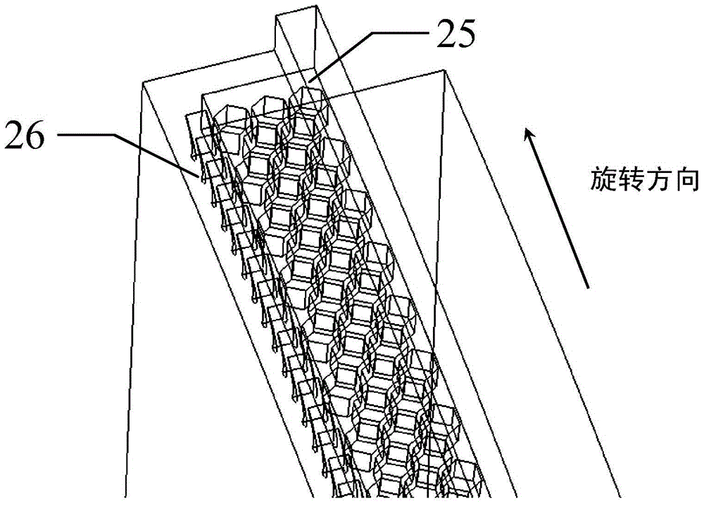
[0034] see Figure 1 to Figure 5 , a radial rim seal structure with damping holes and guide vanes in the present invention, the radial rim seal structure 3 is arranged in the gas turbine rotary-stationary disc cavity 1 or in the gas turbine rotary-rotary disc cavity 2 , including external teeth 8 and radial inner teeth 11 that cooperate with each other; wherein, a number of damping holes 25 are evenly opened on the upper end surface 9 of the inner teeth of the radial inner teeth 11 in the circumferential direction, and in the radial direction of the inner teeth of the radial inner teeth 11 A number of guide vanes 26 are evenly arranged on the circumference of the end face 10 .

[0035]Specifically, referring to Figs. 2 and 3, different from the traditional radial rim seal, the damping radial rim seal of the present invention has stru...


PUM


Abstract

The invention discloses a radial rim sealing structure with damping holes and flow guide blades. The radial rim sealing structure is characterized in that the radial rim sealing structure is arranged in a gas turbine rotor-stator cavity or a gas turbine rotor-rotor cavity and comprises an outer tooth and a radial inner tooth which are matched; a plurality of damping holes are evenly formed in the upper end face of an inner tooth body of the radial inner tooth in the circumferential direction, and a plurality of flow guide blades are evenly arranged on the radial end face of the inner tooth body of the radial inner tooth in the circumferential direction; furthermore, the damping holes are in a cellular shape and are evenly distributed in a sealing tooth face in the circumferential direction; the flow guide blade are arranged on the end face of the sealing radial inner tooth with equal arcs, and the blades are provided with gradually-shrunk channels. The rim sealing structure can effectively lower the high-temperature gas invading degree and improve the sealing performance of rim sealing, and therefore the overheat failure of a turbine disc is avoided, the use amount of low-temperature cooling air flow introduced from the position of an air compressor can also be reduced, and the efficiency of a unit can be improved.

Description

Technical field: [0001] The invention relates to a rim sealing structure, in particular to a rim sealing structure used in the gap between the rotary-static disc cavity or the rotary-rotary disc cavity of gas turbines and high-temperature steam turbines, and has the function of blocking the intrusion of high-temperature mainstream gas. Background technique: [0002] In impeller machinery such as aero-engines, heavy-duty gas turbines, supercritical and ultra-supercritical steam turbines, after the high-temperature gas in the main channel flows through the stator blade nozzle, due to the joint action of the dynamic and static wake and the potential flow field of the rotor blade, it will - The middle area of ​​the static part alternately forms high-pressure flow areas and low-pressure flow areas along the circumferential direction. In the high-pressure flow area, because the pressure of the main flow channel is higher than the internal pressure of the turbine disc cavity, the p...

Claims


Application Information

Patent Timeline
IPC IPC(8): F01D11/10
Inventor 李军高庆李志刚
Owner XI AN JIAOTONG UNIV
Why Eureka
Try Eureka