
Pulse monitoring device for durability of automobile ignition coil and realizing method of pulse monitoring device

A technology of automobile ignition coil and pulse monitoring, which is applied to engine ignition, spark ignition controller, engine components, etc., can solve problems such as the reason for verifying product damage cannot be clearly determined, verification cannot be completed normally, product damage, etc., to achieve protection Safe and effective verification, clear functions, simple and convenient operation

Active Publication Date: 2015-12-09
SPARKTRONIC
View PDF6 Cites 9 Cited by
  • Summary
  • Abstract
  • Description
  • Claims
  • Application Information

AI Technical Summary

Problems solved by technology

During the durability verification, the pulse generating device may generate a fault pulse signal or even a normal high level due to interference and other conditions. These conditions are unpredictable during the test
However, the fault pulse generation is likely to cause fatal damage to the product undergoing durability verification, resulting in the failure to complete the verification normally.
The cause of the damage to the verified product is not yet clearly determined

Method used


Image

  • Pulse monitoring device for durability of automobile ignition coil and realizing method of pulse monitoring device
  • Pulse monitoring device for durability of automobile ignition coil and realizing method of pulse monitoring device
  • Pulse monitoring device for durability of automobile ignition coil and realizing method of pulse monitoring device

Examples


Embodiment Construction

[0023] The technical scheme of the present invention is described in detail below in conjunction with the embodiment shown in the accompanying drawings:

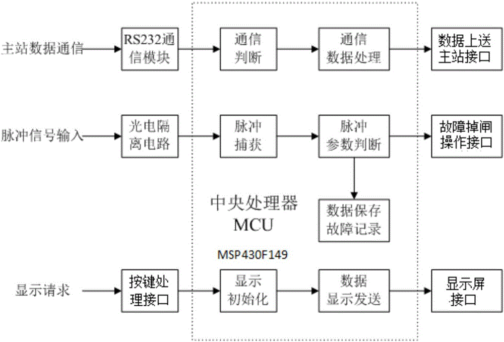
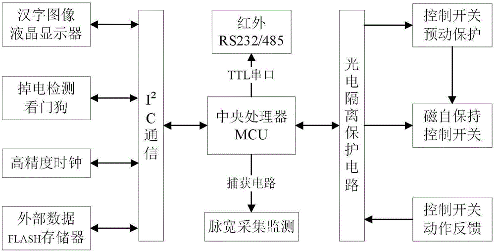
[0024] Such as Figure 1 to Figure 5 As shown, a pulse monitoring device for the durability of an automobile ignition coil includes a central processing unit MCU, a photoelectric isolation circuit, an RS232 communication module, a key processing interface, a data transmission terminal interface, a fault gate operation interface, a display interface, and a photoelectric isolation circuit. , RS232 communication module, button processing interface, data sending terminal interface, fault gate operation interface, and display interface are respectively connected to the central processing unit MCU; the central processing unit adopts a single-chip microcomputer MSP430F149.

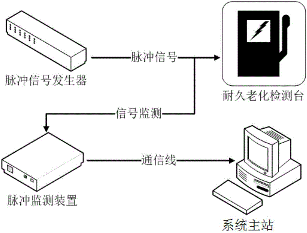
[0025] An automobile ignition coil durable pulse monitoring device of the present invention is bridged on the existing durable aging detection platform, and is...


PUM


Abstract

The invention relates to a pulse monitoring device for durability of an automobile ignition coil and a realizing method of the pulse monitoring device. A photoelectric isolating circuit, an RS232 communication module, a key processing interface, a data submitting main station interface, a fault brake operation interface and a display screen interface are all connected with a central processing unit MCU. An external pulse signal enters the central processing unit MCU through the photoelectric isolating circuit, counting and edge processing are carried out on an input pulse signal by the MCU, so as to complete pulse collection, pulse width, frequency and accumulation monitoring are carried out on the collected pulses, occurrence time and deadline of overfrequency and over-width faults, namely frequency and pulse width exceed preset frequency and pulse width parameters are recorded, external data storage is carried out, so that data analysis in the future is convenient, and a system main station can collect data at any time for comprehensive fault analysis. The pulse monitoring device has the benefits as follows: judgment, storage and failure isolation of signal pulses are realized, safety and effective verification of test equipment products are ensured, the operation s simple and convenient, and timeliness is high.

Description

technical field [0001] The invention relates to a pulse monitoring device and a realization method thereof, in particular to a pulse monitoring device and a realization method thereof for an automobile ignition coil durable stand. Background technique [0002] At present, many electronic products use a pulse generator as a signal input for testing or durability testing of products during testing or routine testing. For example: automotive ignition coil products. When the product is in the process of R & D and durability aging verification, it is generally carried out at 120°C, 500 hours, 50 times per second, that is, 50Hz high temperature, long-term, high-frequency product charging durability aging. During the durability verification, the pulse generating device may generate a fault pulse signal or even a normal high level due to interference and other conditions. These conditions are unpredictable during the test. The generation of fault pulses is likely to cause fatal da...

Claims


Application Information

Patent Timeline
IPC IPC(8): F02P17/00
Inventor 朱溟
Owner SPARKTRONIC
Learn More