Light source structure of automotive LED headlamp

A technology of LED light source and automobile headlight, which is applied in the direction of light source, headlight, electric light source, etc., can solve the problems of high cost, technical difficulty and high cost, and achieve the effect of low cost and difficult selection

Inactive Publication Date: 2015-12-09
束旭初
View PDF8 Cites 1 Cited by
  • Summary
  • Abstract
  • Description
  • Claims
  • Application Information

AI Technical Summary

Problems solved by technology

[0006] The purpose of the present invention is to provide a light source structure of LED automobile headlights to solve the problems in the prior art that it is difficult to realize the high beam or low beam technology of a single LED light source, and the cost is relatively high.

Method used


Image

  • Light source structure of automotive LED headlamp
  • Light source structure of automotive LED headlamp
  • Light source structure of automotive LED headlamp

Examples


Embodiment 1

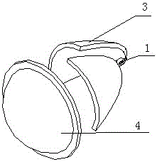
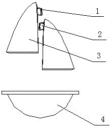
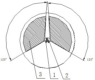
[0030] A light source structure of an LED automobile headlight, such as figure 1 and figure 2 , including LED light source one 1, LED light source two 2, reflective bowl 3, optical lens 4 and light blocking sheet 5, reflective bowl 3 adopts reflective bowl 3 with at least two or more optical centers, LED light source one 1 is arranged on reflective bowl 3 One of the optical centers, the second LED light source 2 is located at the other optical center of the reflective bowl 3, and the first LED light source 1 and the second LED light source 2 are staggered to meet the size of the LED light source. image 3 , the optical lens 4 is located at the light outlet of the reflective bowl 3, the light blocking sheet 5 and the optical lens 4 are distributed along a line with the optical lens 4 as the axis, the optical lens 4 is located at the light outlet of the axis, and the light blocking sheet 5 is located inside the optical lens 4 .

[0031] The first LED light source 1 and the se...

Embodiment 2

[0040] The structure of embodiment two is basically the same as that of embodiment one. The difference between embodiment two and embodiment one is that the reflective bowl 3 of embodiment two adopts an integral reflective bowl 3, LED light source one 1, LED light source two 2 Stagger the setting in the direction perpendicular to the central axis of the optical lens 4, such as Figure 5 .

[0041] In Embodiment 1 and Embodiment 2, the light energy emitted by LED light source one 1 and LED light source two 2 is refracted into a required light pattern through a unified optical lens 4, and the reflective bowl 3 is a reflective surface of light. LED light source one 1, LED The light emitted by the light source 2 is respectively reflected by the reflective bowl 3, and then refracted by the optical lens 4, and the optical lens 4 is located on the outer surface of the light outlet for refraction and appearance effects.

[0042] The LED automobile headlight optical module structure o...


PUM


Abstract

The invention provides a light source structure of an automotive LED headlamp. The light source structure comprises an LED light source I, an LED light source II, a light-reflecting bowl, an optical lens and a light barrier, wherein the light-reflecting bowl is provided with at least two or more optical centers, the LED light source I is arranged at one optical center of the light-reflecting bowl, the LED light source II is arranged at the other optical center of the light-reflecting bowl, the LED light source I and the LED light source II are staggered at an interval of the distance conforming to the size of the LED light sources, the optical lens is arranged at the position of a light outlet of the light-reflecting bowl, and the light barrier and the optical lens are linearly distributed with the optical lens as the axis. The two light sources producing luminous energy are combined, and then the unique optical lens is utilized to form an automotive optical lens assembly completely conforming to the illumination laws and regulations of the automotive headlamp, so that the few-type requirement for a single LED light source of light-distribution laws and regulations of the automotive headlamp is met, and the problem of difficult type selection is solved.

Description

technical field [0001] The invention relates to a light source structure of an LED automobile headlamp. Background technique [0002] Automobile headlights are automobile headlights, which are installed symmetrically on both sides of the front end of the vehicle in order to distinguish the lighting fixtures of the front view when driving at night. LED is a kind of electroluminescent device, which uses solid semiconductor chips as light-emitting materials, and directly emits light through the recombination of carriers to cause photon emission. LED headlights are lighting fixtures manufactured using LEDs as light sources. [0003] The existing LED automotive headlight optical lens module structure generally uses an LED light source, a reflective bowl and an optical lens to form a headlight optical lens assembly. Among them, it is necessary to use an LED light source with a luminous flux greater than 1000LM. The large structure size makes light distribution more difficult. S...

Claims


Application Information

Patent Timeline
Patent Type & Authority Applications(China)
IPC IPC(8): F21S8/10F21V19/00F21V5/04F21V7/04F21W101/02F21W101/10F21Y101/02F21W107/10
CPCF21S41/141F21S41/265F21S41/32F21W2102/00F21W2107/10
Inventor 束旭初
Owner 束旭初
Why Eureka
Try Eureka