

A cooling device for high temperature gas
A cooling device and high-temperature gas technology, which is applied in the direction of lighting and heating equipment, indirect heat exchangers, fixed tubular conduit components, etc., can solve the problems of low space utilization and large occupied volume of the cooling device, and achieve temperature reduction, Small footprint, stable wind pressure and flow
- Summary
- Abstract
- Description
- Claims
- Application Information
AI Technical Summary
Problems solved by technology
Method used
Image

Examples
Embodiment 1
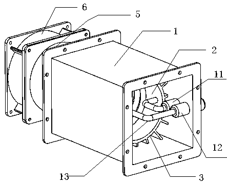
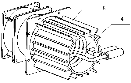
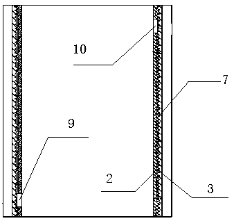
[0014] Embodiment 1: A cooling device for high-temperature gas, the device includes a wind guide cover 1, an inner heat dissipation cylinder 2, an outer heat dissipation cylinder 3, a heat dissipation spiral tube 4, an air duct connector 5 and a fan 6, the inner The heat dissipation cylinder 2 and the outer heat dissipation cylinder 3 are connected by fastening threads 7, and the outer wall of the outer heat dissipation cylinder 3 is provided with heat dissipation fins 8, and the fan 6 is installed on one end of the air duct connector 5 through a fixing piece. The other end of the air duct connector 5 is connected to the air guide cover 1. The air guide cover 1 is hollow and has openings at both ends. The opening of the air guide cover 1 is provided with a flange installation position. The inner cooling cylinder 2 and the outer cooling cylinder 3 are arranged inside the windshield 1, and the opening end of the windshield 1 not equipped with the air duct connector 5 is provided ...
Embodiment 2
[0015] Embodiment 2: A cooling device for high-temperature gas, the device includes a wind guide cover 1, an inner heat dissipation cylinder 2, an outer heat dissipation cylinder 3, a heat dissipation spiral tube 4, an air duct connector 5 and a fan 6, the inner The heat dissipation cylinder 2 and the outer heat dissipation cylinder 3 are connected by fastening threads 7, and the outer wall of the outer heat dissipation cylinder 3 is provided with heat dissipation fins 8, and the fan 6 is installed on one end of the air duct connector 5 through a fixing piece. The other end of the air duct connector 5 is connected to the air guide cover 1. The air guide cover 1 is hollow and has openings at both ends. The opening of the air guide cover 1 is provided with a flange installation position. The inner cooling cylinder 2 and the outer cooling cylinder 3 are arranged inside the windshield 1, and the opening end of the windshield 1 not equipped with the air duct connector 5 is provided ...
Embodiment 3
[0016] Embodiment 3: A cooling device for high-temperature gas, the device includes a wind guide cover 1, an inner heat dissipation cylinder 2, an outer heat dissipation cylinder 3, a heat dissipation spiral tube 4, an air duct connector 5 and a fan 6, the inner The heat dissipation cylinder 2 and the outer heat dissipation cylinder 3 are connected by fastening threads 7, and the outer wall of the outer heat dissipation cylinder 3 is provided with heat dissipation fins 8, and the fan 6 is installed on one end of the air duct connector 5 through a fixing piece. The other end of the air duct connector 5 is connected to the air guide cover 1. The air guide cover 1 is hollow and has openings at both ends. The opening of the air guide cover 1 is provided with a flange installation position. The inner cooling cylinder 2 and the outer cooling cylinder 3 are arranged inside the windshield 1, and the opening end of the windshield 1 not equipped with the air duct connector 5 is provided ...
PUM
 Abstract
Description
Claims
Application Information