
An off-line loading method for weather resistance test of bonded joints

A weather-resistant, off-line technology, applied in the directions of weather resistance/light resistance/corrosion resistance, strength characteristics, and the use of stable tension/pressure to test the strength of materials, etc. problems, to achieve the effect of shortening the test cycle, reducing the cost of the experiment, and improving the efficiency of the experiment

Inactive Publication Date: 2017-06-27
JILIN UNIV
View PDF6 Cites 0 Cited by
  • Summary
  • Abstract
  • Description
  • Claims
  • Application Information

AI Technical Summary

Problems solved by technology

In order to achieve the goal of lightweight automobiles, new materials have been widely used in body structures. Traditional connection methods such as welding and riveting have been greatly challenged, and have been unable to meet the connection requirements of new materials. As an advanced connection method, bonding technology has gained more and more attention
[0003] Due to the influence of various environmental conditions during the use of the bonding structure, the bonding structure needs to be subjected to a weather resistance test. Each cycle of the weather resistance test needs to go through high and low temperature cycles. An experiment takes about 25 to 30 days. The test cycle long
Although the existing testing machines with environmental chambers can carry out the weather resistance test of bonded joints, the testing machine with environmental chambers can only use the online loading method, which can only load one specimen at a time. The weather resistance test requires dozens of test pieces, which greatly prolongs the test period and increases the cost of the test

Method used


Image

  • An off-line loading method for weather resistance test of bonded joints
  • An off-line loading method for weather resistance test of bonded joints
  • An off-line loading method for weather resistance test of bonded joints

Examples


Embodiment Construction

[0040] The present invention will be further described in detail below in conjunction with the accompanying drawings, so that those skilled in the art can implement it with reference to the description.

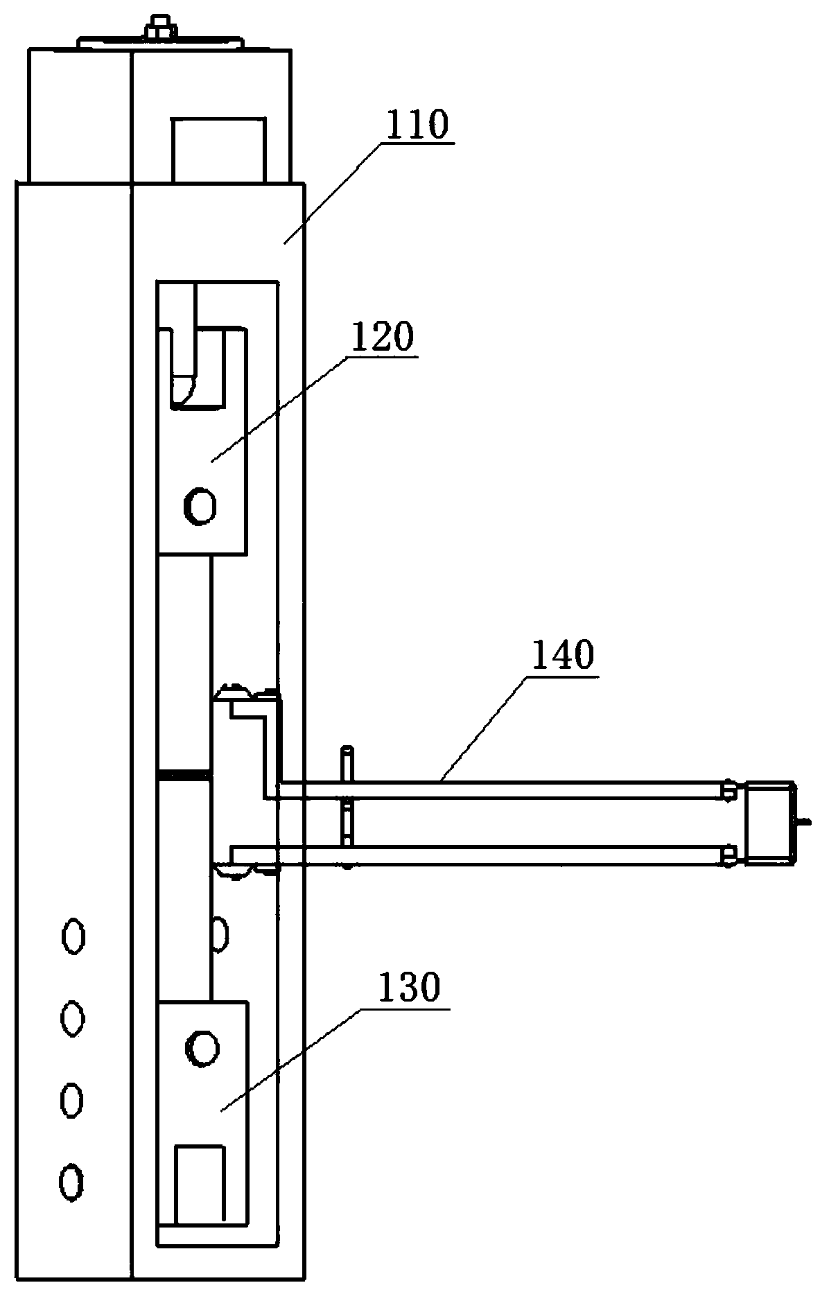
[0041] Such as figure 1 , figure 2 As shown, the present invention provides an off-line loading device for the weather resistance test of bonded joints, including a main frame 110 , an upper double U-shaped connector 120 , a lower double U-shaped connector 130 , a loading device and an extensometer 140 .

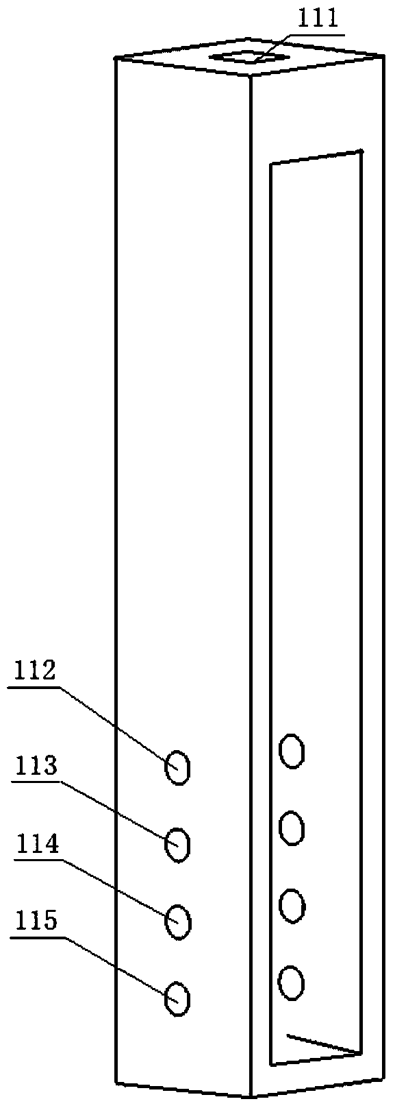
[0042] Such as image 3 As shown, the main frame 110 is set as a hollow frame, that is, the main frame 110 is provided with four sides, upper, lower, left, and right, without two front and back sides, and the middle part is hollow. The main frame 110 is 334mm long, 65mm wide, and 60mm high. The frame thickness on both sides is 10mm. The top of the main frame 110 is provided with a square guide hole 111. The side length of the guide hole 111 is 18.5mm, and the hole depth ...


PUM

PropertyMeasurementUnit
lengthaaaaaaaaaa

Abstract

The invention discloses an off-line loading method for an adhesive joint weather resistance test, comprising the following steps: Step 1: determining the maximum experimental load F of the adhesive joint during the experiment 0 , and set the maximum experimental load F 0 Divided into n levels, n is greater than or equal to 2, and the load of the i-th level is Step 2: Load the bonded joint offline to load F i stop loading; step 3: place the bonded joint together with the off-line loading device in the environmental box, and the temperature in the environmental box is cycled from high temperature, normal temperature to low temperature; step 4: remove the bonded joint, and carry out Tensile test, record the fracture load and fracture strain of the bonded joint; step 5: repeat steps 2 to 4, record the fracture load and fracture strain of the bonded joint under each load level from i to n, and draw the fracture parameter relationship curve. The invention can carry out off-line loading on multiple bonding test pieces at the same time, which greatly shortens the test period, improves the test efficiency and reduces the test cost.

Description

technical field [0001] The invention relates to the field of adhesive strength experiment testing and technology, and in particular relates to an off-line loading method for an adhesive joint weather resistance experiment. Background technique [0002] With the rapid development of adhesives and bonding technology, bonding technology has received extensive attention in the field of vehicle manufacturing. In order to achieve the goal of lightweight automobiles, new materials have been widely used in body structures. Traditional connection methods such as welding and riveting have been greatly challenged, and have been unable to meet the connection requirements of new materials. As an advanced connection method, bonding technology has gained more and more attention. [0003] Due to the influence of various environmental conditions during the use of the bonding structure, the bonding structure needs to be subjected to a weather resistance test. Each cycle of the weather resist...

Claims


Application Information

Patent Timeline
Patent Type & Authority Patents(China)
IPC IPC(8): G01N3/02G01N3/08G01N17/00
Inventor 那景新范以撒谭伟慕文龙秦国峰贺午阳袁正蔡亮刘玉陶士振
Owner JILIN UNIV
Learn More