Multifunctional gas high-pressure in situ Raman test cell and application thereof

An in-situ Raman and test cell technology, applied in Raman scattering, material excitation analysis, etc., can solve the problems of no discovery, few types of in-situ monitoring accessories for Raman spectroscopy, etc., to achieve good performance and expand research fields. Effect

Inactive Publication Date: 2015-12-09
SHANDONG UNIV
View PDF7 Cites 3 Cited by
  • Summary
  • Abstract
  • Description
  • Claims
  • Application Information

AI Technical Summary

Problems solved by technology

[0004] The use of in-situ Raman spectroscopy under extreme conditions to study the special structure and properties of materials has made great progress, but limited to the harsh requirements of extreme conditions for equipment and accessories, there are still few types of Raman spectroscopy in-situ monitoring accessories.
In particular, so far we have not found an accessory that can collect Raman spectra of materials in situ under the combined effects of high temperature, high pressure, special atmosphere, and laser irradiation.

Method used


Image

  • Multifunctional gas high-pressure in situ Raman test cell and application thereof
  • Multifunctional gas high-pressure in situ Raman test cell and application thereof
  • Multifunctional gas high-pressure in situ Raman test cell and application thereof

Examples


Embodiment 1

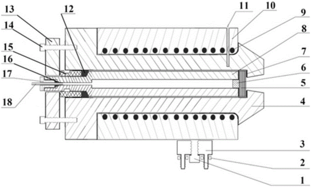
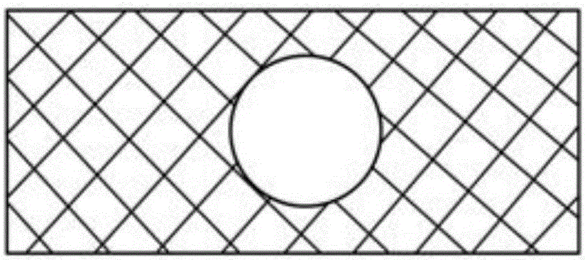
[0053] A multifunctional gas high-pressure in-situ Raman test cell, comprising an outer high-pressure cylinder 4, an inner high-pressure cylinder 8 is arranged in the outer high-pressure cylinder 4, and a window plate 5 is arranged at the front end of the inner high-pressure cylinder 8; The end of the inner high-pressure cylinder 8 is extended to the outside of the outer high-pressure cylinder 4, and is fixedly connected with the end of the outer high-pressure cylinder 4 through fasteners 14; the high-pressure gas source passes through the inner high-pressure cylinder 8 to the The front end of the inner high-pressure cylinder 8 presses the sample 6 to the window 5 .

Embodiment 2

[0055] A multifunctional gas high-pressure in-situ Raman test cell as described in Example 1, the difference is that a thermocouple hole 11 is provided in the outer high-pressure cylinder 4 for inserting a thermocouple.

[0056] A heating part is provided outside the outer high-pressure cylinder 4 . The heating part is a heating pipe 9 .

[0057] An insulation layer 10 is also provided on the outer side of the outer high-pressure cylinder 4 .

Embodiment 3

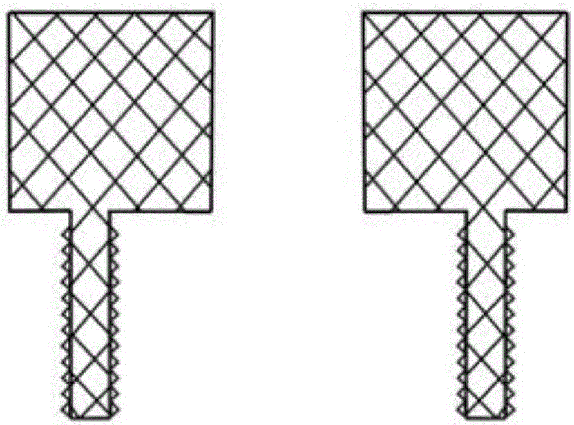
[0059] A multifunctional gas high-pressure in-situ Raman test cell as described in Example 1, the difference is that a height-adjustable base is provided at the bottom of the outer high-pressure cylinder 4 . The height-adjustable base is made of insulating material.

[0060] The height-adjustable base includes a base 3 , connecting screws 1 and fine-tuning nuts 2 .


PUM


Abstract

A multifunctional gas high-pressure in situ Raman test cell comprises an external high pressure cylinder, an internal high pressure cylinder is arranged in the external high pressure cylinder, and the front end of the internal high pressure cylinder is provided with a diaphragm; the tail end of the internal high pressure cylinder is arranged outside the external high pressure cylinder in an extension manner, and is fixedly connected with the tail end of the external high pressure cylinder through a fastener; and a high pressure gas source goes through the internal high pressure cylinder to the front end of the internal high pressure cylinder in order to press a sample to the diaphragm. The test cell can realize in situ test of the Raman spectrum of a material under high temperature, high pressure, special atmosphere, laser irradiation and other extreme conditions. The test cell can be used to test a powder, a block, a high temperature melt, a film and various forms of samples. The test cell can continuously monitor the Raman spectrum of the material in an in-situ manner in the heating, pressurizing and atmosphere changing process in order to realize continuous in-situ tracking of the structure change, the stability and the chemical reaction process of the material.

Description

Technical field: [0001] The invention relates to a multifunctional gas high-pressure in-situ Raman test cell and its application, and belongs to the technical field of the multifunctional Raman test cell for spectrum combined in-situ test. Background technique: [0002] In recent years, with the development of science and technology, in-situ detection research methods have made great progress. Among them, infrared and Raman in-situ detection technologies are developing most rapidly, and the scope of application is constantly expanding, from the initial research on catalytic reaction process to gradually broadening to many interdisciplinary subjects and fields such as chemistry, biology, materials science and clinical medicine. For example, based on the difference between the Raman spectra of single-walled carbon nanotubes and multi-walled carbon nanotubes, Raman spectroscopy is often used to distinguish these two types of carbon nanotubes; In addition, according to the diff...

Claims


Application Information

Patent Timeline
IPC IPC(8): G01N21/65
Inventor 崔得良付现伟刘金利廉刚宋思德王琪珑
Owner SHANDONG UNIV
Why Eureka
Try Eureka