Current detection circuit of switch power supply and switch power supply

A technology of current detection circuit and switching power supply, which is applied in the direction of power supply testing, measuring current/voltage, electrical components, etc. It can solve the problems of unusable, large loss, and low cost, and achieve simple circuit design, reduced loss, and low cost. Effect

Inactive Publication Date: 2015-12-09
EAST GRP CO LTD
View PDF6 Cites 11 Cited by
  • Summary
  • Abstract
  • Description
  • Claims
  • Application Information

AI Technical Summary

Problems solved by technology

[0003] The cost of the current sampling method using the sampling resistor R1 is relatively low, but the detection accuracy is poor, especially when detecting large currents, not only the accuracy is poor, but the loss is also large
On the other hand, due to the use of resistance sampling, in order to select the voltage reference, the ground of the control system needs to share the ground with the secondary ground of the power system, which increases the difficulty of system design
The use of Hall sensors can improve accuracy, but the cost is high and cannot be used in low-cost solutions

Method used


Image

  • Current detection circuit of switch power supply and switch power supply
  • Current detection circuit of switch power supply and switch power supply

Examples


Embodiment 1

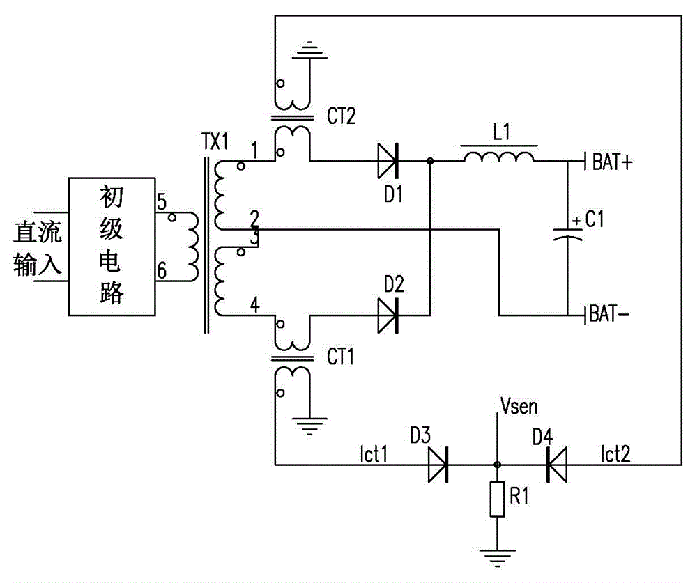
[0017] A current detection circuit of a switching power supply in this embodiment includes a first current transformer, a second current transformer, a sampling resistor and a control system, and the first current transformer outputs the secondary of the transformer to the first rectifier diode of the upper side The first current is converted into a small current and supplied to the sampling resistor. The second current transformer converts the secondary output of the transformer to the second current of the lower rectifier diode into a small current and then supplies the sampling resistor. The control system obtains the voltage across the sampling resistor , and converted to an output signal.

[0018] In this embodiment, current detection is performed by sampling the sampling resistance at the DC output end of the transformer in the prior art, and the current detection is performed by using a current transformer at the AC output end of the transformer. The ingenious selection ...

Embodiment 2

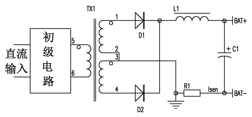
[0030] A switching power supply includes a transformer, an upper rectifier diode and a lower rectifier diode connected to the secondary side of the transformer, and it also includes the current detection circuit described in Embodiment 1.

[0031] The primary of the first current transformer is connected between the upper output pin of the secondary of the transformer and the upper rectifier diode, and the primary of the second current transformer is connected to the lower output pin of the secondary of the transformer and the lower rectifier diode. Through the ingenious selection of the current detection point, the current transformer can be used to participate in the current detection. Its cost is low, and it can also meet the high precision requirements for large current detection.

[0032]One end of the secondary of the first current transformer is connected to one end of the sampling resistor, the other end of the secondary of the first current transformer is grounded, an...


PUM


Abstract

The invention discloses a current detection circuit of a switch power supply and a switch power supply, relating to the current detection technology field. The current detection circuit of the switch power supply comprises a first current mutual inductor, a second current mutual inductor, a sampling resistor and a control system; the second current mutual inductor converts second current which is transmitted from the secondary of a transformer TX1 to an upper side diode to small current which is then supplied to a sampling resistor; the second current mutual inductor converts second current which is transmitted from the secondary of a transformer to an upper side diode to small current which is then supplied to the sampling resistor; and the control system obtain voltage on two ends of the sampling resistor which is converted to corresponding current. Through the clever choice of the current detection point, the current mutual inductor can be used to participate in current detection, the current mutual inductor can convert big current to the small current, and the small current can be supplied to the sampling resistor, which greatly reduce the loss of the sampling resistor, reduces the cost, and improves the precision and design difficulty. Besides, the switch power supply can realize the detection of the charging current, which can benefit the control of the charging current.

Description

technical field [0001] The invention relates to the technical field of current detection, in particular to a current detection circuit of a switching power supply and a switching power supply. Background technique [0002] In new energy vehicles, batteries are often used. After the energy of the batteries is exhausted, a charger needs to be used to charge the batteries. Current chargers often use a switching power supply as an energy conversion device, and the input is taken from the AC power grid, which is converted into DC power after isolation by a high-frequency transformer. In order to realize the control of the charging current, it is necessary to detect the output current of the charger. Since the output current is DC, current sampling resistors are often used to sample the current, such as figure 1 As shown, the switching power supply includes a transformer TX1, a diode D1 (called the upper side rectifier diode), a diode D2 (called the lower side rectifier diode), ...

Claims


Application Information

Patent Timeline
Patent Type & Authority Applications(China)
IPC IPC(8): G01R19/00G01R31/40H02M3/26
Inventor 陈书生
Owner EAST GRP CO LTD
Why Eureka
Try Eureka