High-voltage DC transmission fault recording and alarming device

A high-voltage direct current transmission and alarm device technology, applied in the direction of measuring devices, measuring electricity, measuring electrical variables, etc., can solve the problem that the performance of the fault recorder cannot bear network data packets, and the fault analysis and fault recorder of the DC transmission system cannot be used Data cannot be saved and other problems, to achieve the effect of reducing costs, reducing performance requirements, and reducing burdens

Inactive Publication Date: 2015-12-09
SHANGHAI MUNICIPAL ELECTRIC POWER CO
View PDF5 Cites 2 Cited by
  • Summary
  • Abstract
  • Description
  • Claims
  • Application Information

AI Technical Summary

Problems solved by technology

Although the converter station is equipped with a fault recorder in the AC and DC systems, due to the particularity of the converter station, the faults of equipment in different areas have their own characteristics, and the fault form and mechanism of the DC core equipment are different from those in the AC system. There is a big difference in the general components of the AC system, and the fault diagnosis and analysis software usually used in the AC system cannot be used for the fault analysis of the DC transmission system. In addition, when the analyst manually analyzes the fault recorder data, the fault detected by different fault recorders Combined analysis of electrical parameters, or comparative analysis of the data recorded by the same fault recorder at different times and under different fault conditions, is conducive to analyzing the cause of the abnormality or fault.
However, due to the differences in the consequences of different DC protection actions
[0003] In addition, because the data of the fault recorder cannot be saved, and the performance of the fault recorder cannot withstand some continuous network data packets, it also affects the reliability of the fault recorder

Method used


Image

  • High-voltage DC transmission fault recording and alarming device

Examples


Embodiment Construction

[0020] The present invention will be described in detail below in conjunction with the accompanying drawings and specific embodiments. This embodiment is carried out on the premise of the technical solution of the present invention, and detailed implementation and specific operation process are given, but the protection scope of the present invention is not limited to the following embodiments.

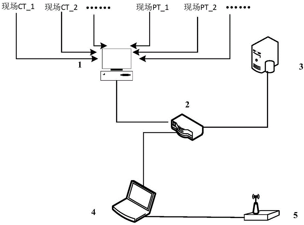
[0021] A high-voltage direct current transmission fault recording and alarm device, such as figure 1 As shown, it includes a fault recorder 1 for collecting fault recorder data, an analysis terminal 4 for drawing a fault data curve according to the fault recorder data, and a GSM module 5 for connecting a mobile terminal. The fault recorder 1, The analysis terminal 4 and the GSM module 5 are connected sequentially. The fault recorder and alarm device also includes a server 3 and a router 2. The fault recorder 1, the server 3 and the analysis terminal 4 are connected to each other throu...


PUM


Abstract

The invention relates to a high-voltage DC transmission fault recording and alarming device. The device comprises a fault recorder for collecting fault record data, an analysis terminal for drawing a fault data curve according to the fault record data, and a GSM module connecting to a mobile terminal. The fault recorder, the analysis terminal and the GSM module are connected in sequence. The current and voltage data of faults of a high-voltage DC transmission system is collected by the fault recorder and serves as fault record data, and alarming signals and the fault data curve drawn by the analysis terminal are sent to the mobile terminal by the GSM module when the high-voltage DC transmission system malfunctions. Compared with the prior art, the high-voltage DC transmission fault recording and alarming device has the advantages that the analysis terminal draws the fault data curve on the basis of the fault record data, and the curve is sent to a mobile terminal carried by a worker through the GSM module, in this way, instant alarming and feedback can be achieved, a fault report can be quickly produced, the workload of workers is reduced, and the work efficiency is improved.

Description

technical field [0001] The invention relates to a power system operation and maintenance technology, in particular to a high-voltage direct current transmission fault recording and alarm device. Background technique [0002] With the continuous development of the scale of cross-regional power grids, ultra-high voltage converter stations and UHV converter stations are playing an increasingly important role in the power grid, and the safety and reliability requirements of the power grid for converter stations are also getting higher and higher. Once the converter station in the HVDC transmission system has an abnormal situation or a fault lockout, it will cause certain disturbances and impacts to the power system at the receiving end or the sending end, threatening the safe and stable operation of the system. Once a disturbance or other abnormal situation occurs in the system, the fault recorder in the power grid will meet the relevant trigger conditions and record the data. ...

Claims


Application Information

Patent Timeline
Patent Type & Authority Applications(China)
IPC IPC(8): G01R31/00
Inventor 钱程晨王和杰倪汝冰阴春晓周徐达武垣成
Owner SHANGHAI MUNICIPAL ELECTRIC POWER CO
Why Eureka
Try Eureka