Transient state polarization radar waveform acquisition method and radar signal transmission method based thereon

A technology of transient polarization and radar waveforms, applied in the field of constant modulus phase encoding, which can solve problems such as high side lobes of transmitted waveforms, long waveform convergence time, etc.

Inactive Publication Date: 2015-12-09
HARBIN INST OF TECH
View PDF3 Cites 10 Cited by
  • Summary
  • Abstract
  • Description
  • Claims
  • Application Information

AI Technical Summary

Problems solved by technology

[0005] The purpose of the present invention is to solve the problem that the transient polarization radar emission waveform obtained by the existing method has high sidelobe and lon

Method used


Image

  • Transient state polarization radar waveform acquisition method and radar signal transmission method based thereon
  • Transient state polarization radar waveform acquisition method and radar signal transmission method based thereon
  • Transient state polarization radar waveform acquisition method and radar signal transmission method based thereon

Examples


specific Embodiment approach 1

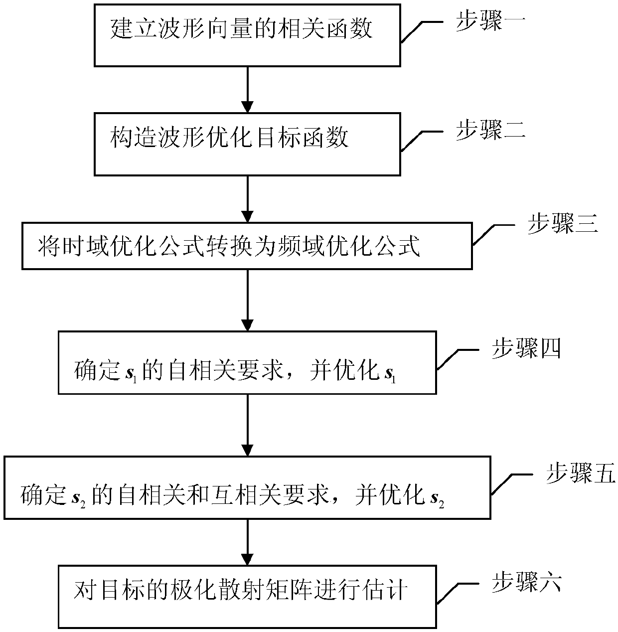
[0057] Specific implementation mode 1: Combination figure 1 To illustrate this embodiment, the method for obtaining a transient polarization radar waveform described in this embodiment includes the following steps:

[0058] Step 1. Use the shift matrix to establish the correlation function of the waveform vector,

[0059] The baseband discrete form of the horizontally polarized channel and the vertically polarized channel of the emission waveform are respectively s 1 And s 2 , The aperiodic correlation function of the sequence at the delay n is expressed as follows:

[0060] r n (s 1 ,s 2 )=s 1 H U(n)s 2 (1)

[0061] U ( n ) = I N X N , n = 0 0 I ( N - n ) X ( N - n ) 0 0 , 0 n N U T ( - n ) , - N n 0 0 N X N , | n | ≥ N - - - ( 2 )

[0062] among them Represents the N-dimension...

specific Embodiment approach 2

[0133] Specific implementation manner two: combination Figure 3 to 9 This embodiment is described. This embodiment is a simulation verification of the method for obtaining a transient polarization radar waveform described in the first embodiment.

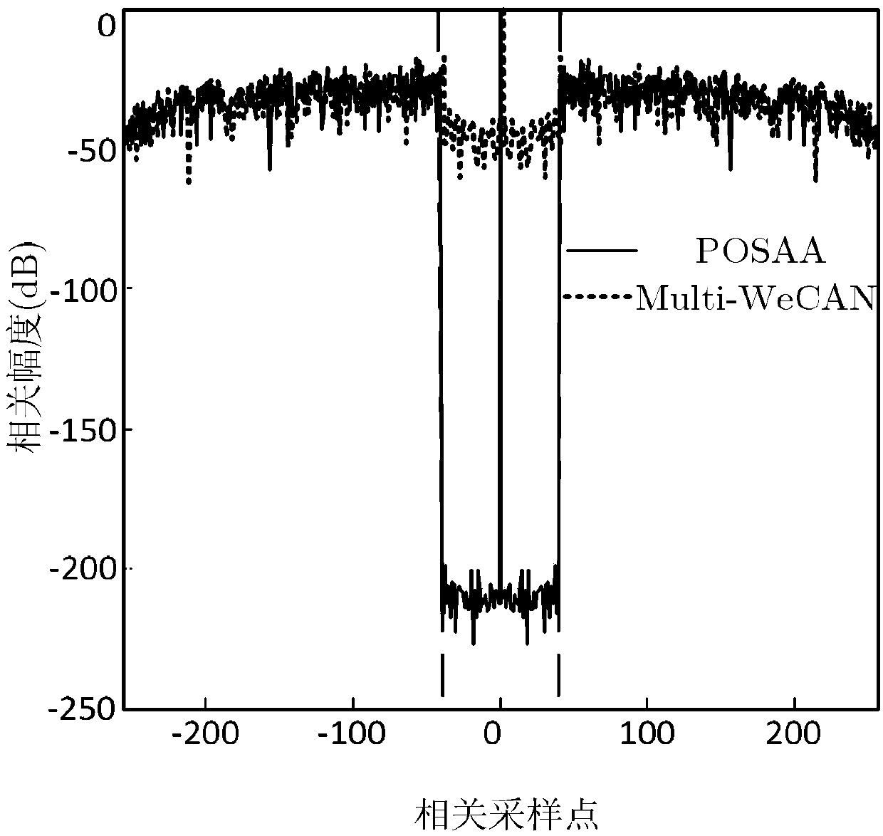
[0134] Simulation experiment 1: Given suppression interval 1-40, check the correlation characteristics of the obtained waveform, here is mainly related to the Multi- in the literature Designingunimodularsequencesetswithgoodcorrelations-includinganapplicationtoMIMOradar.HeH,StoicaP,andLiJ.IEEETransactionsonSignalProcessing,2009,57(11):4391-4405 SequenceWeightedCyclicAlgorithm–New (Multi-WeCAN) method is compared.

[0135] Simulation conditions: set the autocorrelation sequence at 0 delay as the center, the correlation interval of 1-40 as the suppression interval, and the sequence length as 256.

[0136] image 3 with Figure 4 Shows the autocorrelation sidelobes of the waveform obtained by the method of the present invention and the wavef...

specific Embodiment approach 3

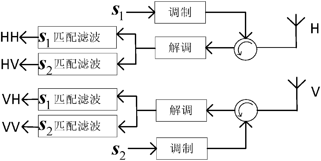
[0148] Specific implementation mode three: combination figure 2 To explain this embodiment, this embodiment is a radar signal transmission method based on the transient polarization radar waveform acquisition method described in Embodiment 1, and the method is:

[0149] At the transmitting end: to s 1 And s 2 Modulate, and the modulated s 1 And s 2 Launched through the horizontal polarization channel and the vertical polarization channel respectively;

[0150] At the receiving end: demodulate the signal from the horizontal polarization channel, and divide the demodulated signal into two channels, and perform s respectively 1 Matched filtering and s 2 Matched filtering to obtain the signal components received by the horizontal polarization channel during horizontal and vertical polarization transmission respectively; demodulate the signal from the vertical polarization channel, and divide the demodulated signal into two channels, respectively. 1 Matched filtering and s 2 Matched filt...


PUM


Abstract

A transient state polarization radar waveform acquisition method and a radar signal transmission method based thereon relate to a method for designing constant module phase encoding enabling a transient state polarization radar to meet good related performance. The methods provided herein aim to solve the problems of high side lobe of the transient state polarization radar waveform and the existing influence of reflected signals of other distant units received by the radar to the reflected signals of a target distant unit. In this invention, firstly, a shift matrix is utilized to establish a function related to a waveform vector; a strong scattering body and a position of a target in a radar scene are ensured and a distant side lobe section needed to be suppressed is estimated so as to construct a waveform optimization objective function; a time-domain optimization formula is transformed into a frequency-domain optimization formula; lastly, self-correlation and cross-correlation requirements of two waveforms are ensured and the waveforms are optimized; and the two waveforms are used as radar signals for transmitting and receiving. According to the invention, the related side lobe can be suppressed; the distant side lobe interference between various scattering bodies distributed along the distant direction is reduced; and the reflected signals of the other distant units are suppressed, thus improving the signal ratio.

Description

Technical field [0001] The invention belongs to the technical field of radar communication, and particularly relates to a method for obtaining a constant modulus phase encoding that a transient polarization radar satisfies good correlation performance. Background technique [0002] With the increasing complexity of the radar environment, obtaining waveforms with low correlation side lobes is receiving more and more attention from scholars (see literature: WaveformOptimizationforMIMORadarinColoredNoise:FurtherResultsforEstimation-OrientedCriteria.TangB,TangJ,PengYN.IEEETransactionsonSignalProcessing,2012,60(3): 1517-1522; Signals synthesis and receiver design for MIMOradarimaging. LiJ, StoicaP, ZhengXY. IEEETransactionson Signal Processing, 2008, 56(8): 3959-3968.). In the field of communications and radar, the transmitted waveform is required to have low side lobes near the autocorrelation main lobe, and at the same time, it is required to have extremely low cross-correlation amp...

Claims


Application Information

Patent Timeline
IPC IPC(8): G01S7/28G01S7/282G01S7/285
CPCG01S7/2813G01S7/282G01S7/285
Inventor 赵宜楠赵占锋姜智卓冯翔周志权
Owner HARBIN INST OF TECH
Why Eureka
Try Eureka