In-vivo implanted ossiphone vibrating device

A vibration device and implant technology, applied in the field of medical equipment, can solve the problems of large vibration contact area of ​​vibrating plate or vibrating plate, low vibration frequency of vibrating plate or vibrating plate, unsuitable for high-frequency vibration, etc., and achieve useful work output Large, high vibration efficiency, large amplitude effect

Active Publication Date: 2015-12-09
YIERKANG HEARING SCI & TECH SHANGHAI CO LTD
View PDF3 Cites 3 Cited by
  • Summary
  • Abstract
  • Description
  • Claims
  • Application Information

AI Technical Summary

Problems solved by technology

[0009] The core part of the bone conduction hearing aid implanted in the body is the vibration device. The vibration device of the existing bone conduction hearing aid implanted in the body is a vibrating plate or a vibrating plate. The vibrating plate or vibrating plate vibrates in a changing magnetic field to make the skull vibrate, but there is The following disadvantages: 1. The amplitude of the vibrating plate or vibrating plate

Method used


Image

  • In-vivo implanted ossiphone vibrating device
  • In-vivo implanted ossiphone vibrating device
  • In-vivo implanted ossiphone vibrating device

Examples


Embodiment 1

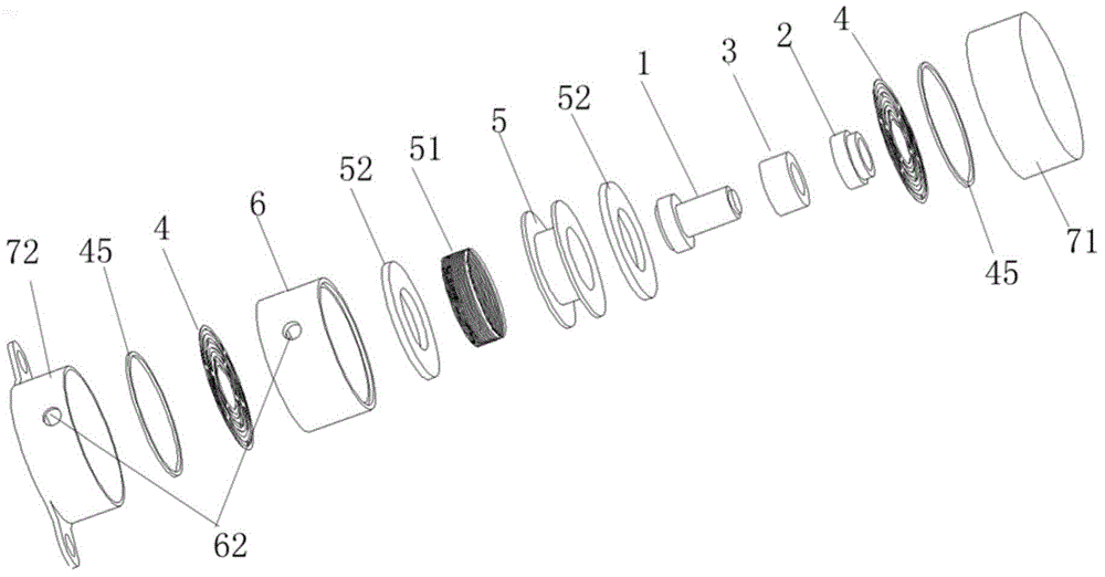
[0062] Please refer to figure 1 , figure 1 It is a schematic diagram of the explosive structure of a bone conduction hearing aid vibration device implanted in the body of the present invention. A bone conduction hearing aid vibration device implanted in the body, the vibration device includes a first vibrator 1, a second vibrator 2, a reed 4, a reed pressure plate 45, a magnetic conductive sheet 52, a coil frame 5, a coil 51, a magnet 3, Fixed frame 6, shell 7.

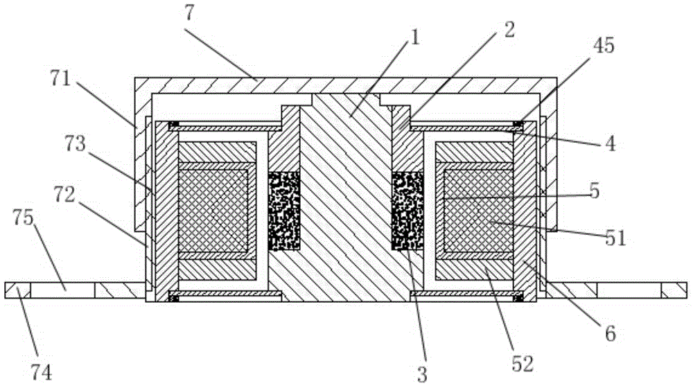
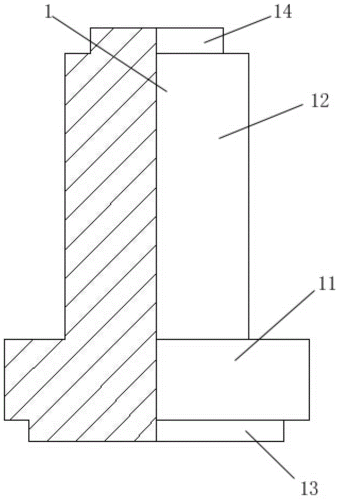
[0063] Please refer to figure 2 , figure 2 It is a schematic diagram of the assembly of a bone conduction hearing aid vibration device implanted in the body of the present invention. The first vibrator 1 has a stepped structure, and the first vibrator 1 includes a bottom cylinder 13, a first boss 11, a second boss 12, and a top cylinder 14; the bottom cylinder 13, the first boss The platform 11, the second boss 12, and the top cylinder 14 are integrally formed at one time; the bottom cylinder 13, the first boss...

Embodiment 2

[0076] Please refer to Figure 7 , Figure 7 It is an assembly schematic diagram of another implanted bone conduction hearing aid vibration device of the present invention. This embodiment is basically the same as Embodiment 1, except that the end face of the fixing plate 74 is flush with the end face of the lower cover 72. Compared with Embodiment 1, this embodiment is easy to operate during installation.

Embodiment 3

[0078] Please refer to Figure 8 , Figure 8 It is a schematic diagram of the explosive structure of another implanted bone conduction hearing aid vibration device of the present invention. A bone conduction hearing aid vibration device implanted in the body, the vibration device includes a first vibrator 1, a second vibrator 2, a reed 4, a reed pressure plate 45, a magnetic conductive sheet 52, a coil frame 5, a coil 51, a magnet 3, Fixed frame 6, shell 7;

[0079] Please refer to Figure 9 , Figure 9It is an assembly schematic diagram of another implanted bone conduction hearing aid vibration device of the present invention. The first vibrator 1 is assembled on the upper end surface of the magnet 3; the outer periphery of the magnet 3 is provided with a coil bobbin 5; the coil bobbin 5 is wound with a coil 51; the two ends of the coil bobbin 5 are provided with magnetic conductive sheets 52; The magnetically conductive sheet 52 is a stepped structure, and the end face ...


PUM

PropertyMeasurementUnit
Diameteraaaaaaaaaa

Abstract

The invention relates to an in-vivo implanted ossiphone vibrating device. The vibrator comprises a first vibrator, a second vibrator, leaf springs, leaf spring pressing plates, magnetic conductive plates, a coil framework, a coil, a magnet, a holder and a shell; the first vibrator is of a stepped structure and comprises a bottom cylinder, a first lug boss, a second lug boss and a top cylinder; the second vibrator and the magnet are assembled on the peripheral surface of the second lug boss; the first vibrator is arranged in the holder; a wire outlet is formed in a sidewall of the holder; the holder is of a structure open at both ends and counter bored holes are formed in the two ends; the leaf springs and the leaf spring pressing plates are glued on the counter bored holes, respectively; the coil framework is further assembled on the peripheral surface of the magnet; the coil is wound around the coil framework; the magnetic conductive plates are assembled on the two end faces of the coil framework; the shell comprises an upper cover, a lower cover and a fixed plate. The in-vivo implanted ossiphone vibrating device has the advantages of available high-frequency vibration, high vibration efficiency and large vibration amplitude.

Description

technical field [0001] The invention relates to the technical field of medical devices, in particular to a bone conduction hearing aid vibration device implanted in the body. Background technique [0002] There are two forms of sound transmission, air conduction and bone conduction, but the final place where the sound is heard is the auditory system of the inner ear. The following are two different transmission paths for sound. Human speech and the sound from TV and radio are transmitted to the external auditory canal by vibrating the surrounding air, and then transmitted to the middle ear through the tympanic membrane. The vibration will become stronger in the middle ear, and finally touch the cochlea floating in the lymphatic fluid. Auditory hair cells and auditory nerve, so that you can hear the sound. Bone conduction does not pass through the outer ear and middle ear, but converts the audio signal into a vibration signal, which is directly transmitted to the inner ear ...

Claims


Application Information

Patent Timeline
IPC IPC(8): H04R25/00
Inventor 朱胜利干国琴张天宇戴培东
Owner YIERKANG HEARING SCI & TECH SHANGHAI CO LTD
Why Eureka
Try Eureka