Reluctance rotor with runup aid

A reluctance motor and magnetic flux technology, applied in the rotor field, can solve the problems of rotor electrical loss and low efficiency, and achieve the effect of optimizing the driving characteristics

Inactive Publication Date: 2015-12-09
SIEMENS AG
View PDF9 Cites 7 Cited by
  • Summary
  • Abstract
  • Description
  • Claims
  • Application Information

AI Technical Summary

Problems solved by technology

However, asynchronous motors have the disadvantage that their efficiency is generally lower than that of synchronously operating reluctance motors because of electrical losses in the rotor due to the constant slip between the stator's rotating field and the rotor

Method used


Image

  • Reluctance rotor with runup aid
  • Reluctance rotor with runup aid
  • Reluctance rotor with runup aid

Examples


Embodiment Construction

[0030]The embodiments described next are preferred designs of the present invention. However, in the exemplary embodiment, the described components of the embodiment represent the corresponding individual features of the invention considered independently of each other, which also improve the invention independently of each other and are thus also shown individually or in addition Combinations are considered to be part of the present invention. Furthermore, the embodiments described can also be supplemented by further features of the invention already described.

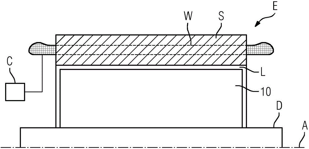
[0031] exist figure 1 An electric machine E is shown in , where it can be, for example, a synchronous reluctance machine or an asynchronous machine. exist figure 1 In , the axis of rotation A is also the axis of symmetry shown in the figure. The electric machine E comprises a stator S in which windings W of electric coils are arranged, wherein in figure 1 Only one of the windings W is shown in . The windings W ...


PUM


Abstract

The invention relates to a rotor (10) for a reluctance motor, wherein the rotor (10) has a laminate stack (14) having layers (16), each of which has a plurality of flux-conducting sections (24) formed in each case by a magnetically conductive rotor lamination (18) and extending transversely to a corresponding q axis (30), wherein the flux-conducting sections (24) are separated from one another by nonmagnetic flux barrier regions (22). The invention is based on the problem of providing the rotor (10) with a runup aid. For this purpose, an electrically conductive and non-ferromagnetic filler material is arranged in a plurality or all of the flux barrier regions (22) of the layers (16), by means of which filler material the flux barrier regions (22) of adjacent layers are electrically connected to one another so that cage bars (34) of a rotor cage of the rotor (10) which extend axially parallel or skewed with respect to the axis of rotation (A) are formed by the filler material in the flux barrier regions (22).

Description

technical field [0001] The invention relates to a rotor for a reluctance machine. The rotor has a lamination core, the individual lamination layers of which have strip-shaped flux-conducting sections for conducting the magnetic flux between the d-axis of the rotor. For this purpose, the flux-conducting sections extend transversely to the respective q-axis of the rotor and are separated from one another by non-magnetic flux-blocking regions. Background technique [0002] A rotor of this type is known for example from US5818140A. The flux-locked region thus forms a cavity in the rotor. [0003] This invention provides a further improvement of the rotor, which is described in European Patent Application No. EP13163492.5 filed on 12.04.2013. Supports are therefore arranged in the flux-locking area, in order to support the rotor against centrifugal forces, since the provision of an air-locking area in the lamination stack reduces its mechanical robustness. Furthermore, the ro...

Claims


Application Information

Patent Timeline
Patent Type & Authority Applications(China)
IPC IPC(8): H02K19/14H02K1/24
CPCH02K1/246H02K19/14H02K1/24H02K15/02H02K19/06H02K17/165
Inventor 克劳斯·比特纳马尔科·塞尔尼拉尔夫·菲舍尔马蒂亚斯·瓦尔穆特
Owner SIEMENS AG
Why Eureka
Try Eureka