Eureka AIR delivers breakthrough ideas for toughest innovation challenges, trusted by R&D personnel around the world.

Ball mill tube, ball mill with ball mill tube and manufacturing method of ball mill

A ball mill and cylinder technology, applied in the field of mining machinery related technical equipment, can solve the problems of difficult processing, poor concentricity of the horizontal cylinder, and high construction cost, and achieve the effects of reducing production cost and difficulty, small driving force, and improving precision.

Inactive Publication Date: 2015-12-16
JINAN JIGANG IRON ALLOY FACTORY
View PDF8 Cites 4 Cited by
  • Summary
  • Abstract
  • Description
  • Claims
  • Application Information

AI Technical Summary

Problems solved by technology

Its main bearing adopts sliding bearings, but it is difficult to manufacture and process such extra-large special bearings, and the cost is high. The weight of the cylinder is supported on the bearings at both ends, which consumes a lot of energy, resulting in high production costs.
[0003] Specifically: the current horizontal ball mill often has a long cylinder, and the concentricity of the horizontal cylinder is poor due to the use of end supports, and the ball mill shakes greatly when it is running at high speed
At the same time, the cylinder is a circular shape made of steel plate. The longer the cylinder of the ball mill, the thicker the steel plate required, the higher the requirements for the rolling equipment, and the difficulty in making the cylinder.

Method used


Image

  • Ball mill tube, ball mill with ball mill tube and manufacturing method of ball mill
  • Ball mill tube, ball mill with ball mill tube and manufacturing method of ball mill
  • Ball mill tube, ball mill with ball mill tube and manufacturing method of ball mill

Examples


Embodiment

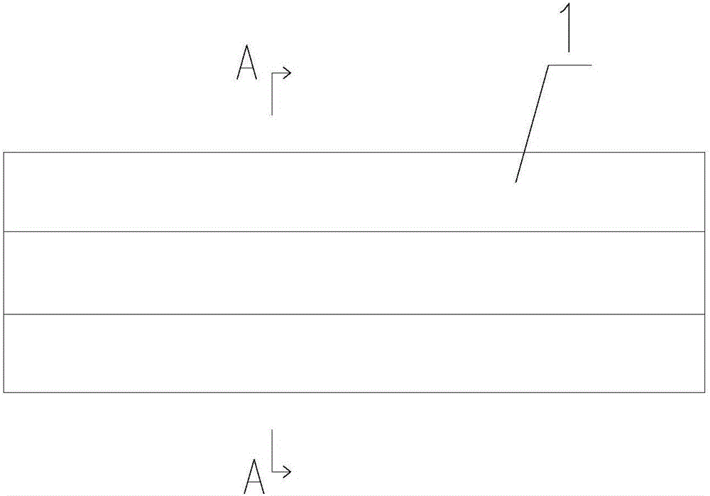
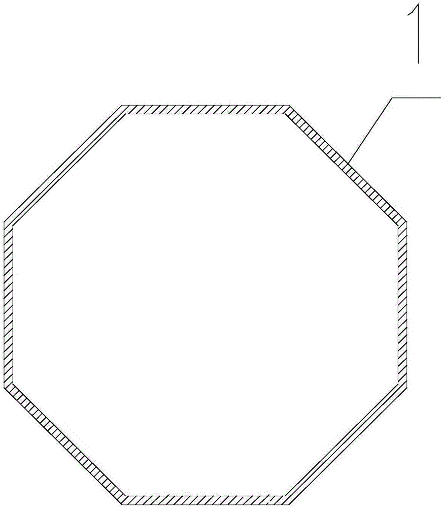
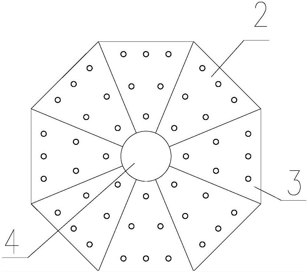
[0040] Embodiment: a kind of ball mill barrel, its structure reference Figure 1-3 As shown, it includes an end liner 2 and a plurality of cylinder liner 1 fixedly connected to the edge of one side of the end liner 2;

[0041] The end liner 2 has a polygonal structure, and the space formed by the end liner 2 and the cylinder liner 1 is a ball mill for materials; the end liner 2 is welded by a plurality of base plates 3 with the same structure.

[0042] Preferably, the barrel of the ball mill is a regular polygonal structure. Such as regular hexagonal, regular octagonal or regular dodecagonal structures.

[0043] The best choice is that the ball mill and the barrel have an octagonal structure. That is: the outer edges of the end linings 2 at both ends are octagonal structures, and the eight sides of the end linings 2 are respectively fixedly connected with a rectangular cylinder lining 1, and the adjacent cylinder linings 1 are welded to form confined space. Wherein, there ...


PUM


Abstract

The invention relates to a ball mill tube, a ball mill with the ball mill tube, and a manufacturing method of the ball mill. The ball mill tube mainly comprises an end lining board, and a plurality of tube lining boards which are fixedly connected with the end lining board, wherein the end lining board is of a polygonal structure; a closed space formed by the end lining board and the tube lining boards is used as a ball mill chamber for materials. The ball mill mainly comprises the aforementioned tube; a chute and a large gear ring are arranged at the outer side of the tube; a feeding port and a discharging port are correspondingly formed in two ends of the tube; the chute is supported through supporting wheels which are fixedly connected to a base; a power mechanism for driving the tube to rotate through the large gear ring is arranged on the base. According to the ball mill tube, a complete new structure is designed, so that the tube is basically not limited by a rolling device during the production, and the production cost and energy consumption can be greatly decreased.

Description

technical field [0001] The invention relates to the technical equipment field related to mining machinery, in particular to a ball mill cylinder, a ball mill with the cylinder and a manufacturing method. Background technique [0002] At present, most common ball mills use circular cylinders, and hollow shaft supports are installed at both ends. Its main bearing adopts sliding bearing, but it is difficult to manufacture and process this extra-large special bearing, and the cost is high. The weight of the cylinder is supported on the bearings at both ends, which consumes a lot of energy, resulting in high production cost. [0003] Specifically: the current horizontal ball mill often has a long cylinder, and the concentricity of the horizontal cylinder is poor due to the use of end supports, and the ball mill shakes greatly when it is running at high speed. At the same time, the cylinder is a circular shape made of steel plate. The longer the cylinder of the ball mill, the thi...

Claims


Application Information

Patent Timeline
Patent Type & Authority Applications(China)
IPC IPC(8): B02C17/00B02C17/22B02C17/24B02C17/18
Inventor 李明波江鹏孙勇刘长利
Owner JINAN JIGANG IRON ALLOY FACTORY
Why Eureka
Eureka Blog
Learn More