Carpentry tooth slotting machine

A combing machine and woodworking technology, which is applied to wood processing equipment, manufacturing tools, circular saws, etc., can solve the problems of high cost, increased cost, and increased maintenance cost, and achieve high work efficiency, convenient heat dissipation, and improved safety. Effect

Inactive Publication Date: 2015-12-16
TIANJIN XIANGYUAN FURNITURE CO LTD
View PDF0 Cites 5 Cited by
  • Summary
  • Abstract
  • Description
  • Claims
  • Application Information

AI Technical Summary

Problems solved by technology

[0002] With the rapid development of the economy, people's awareness of environmental protection has been enhanced, and the utilization of wood has been strictly controlled. Excessive logging is strictly prohibited, and it is necessary to meet the needs of economic development and control product costs. In this market environment, It is necessary to improve the utilization rate of wood, to carry out secondary recycling of wood or to lengthen short wood, which is a mature technology at present, and combing machine and lengthening machine can be used together to lengthen short wood. Moreover, the strength and hardness of the lengthened wood planks are the same as those of the original long wood, which can meet the needs of processing and production. At present, the comb machines on the market are automated and equipped with automatic feeding systems. The cost increase is too high, and there are also semi-automatic ones. Positioning devices such as cylinders are installed, but the cylinder needs to be equipped with an air pump, and the cost of an air pump is also relatively high. In addition, the air pressure return line must be installed to cooperate with the air pump, and the stability of the air pressure must be ensured. The related equipment and maintenance costs also increase a lot. To solve this problem , it is necessary to provide a woodworking comb machine with simpler structure and high efficiency

Method used


Image

  • Carpentry tooth slotting machine
  • Carpentry tooth slotting machine

Examples


Embodiment Construction

[0015] Specific embodiments of the present invention will be described in detail below in conjunction with the accompanying drawings.

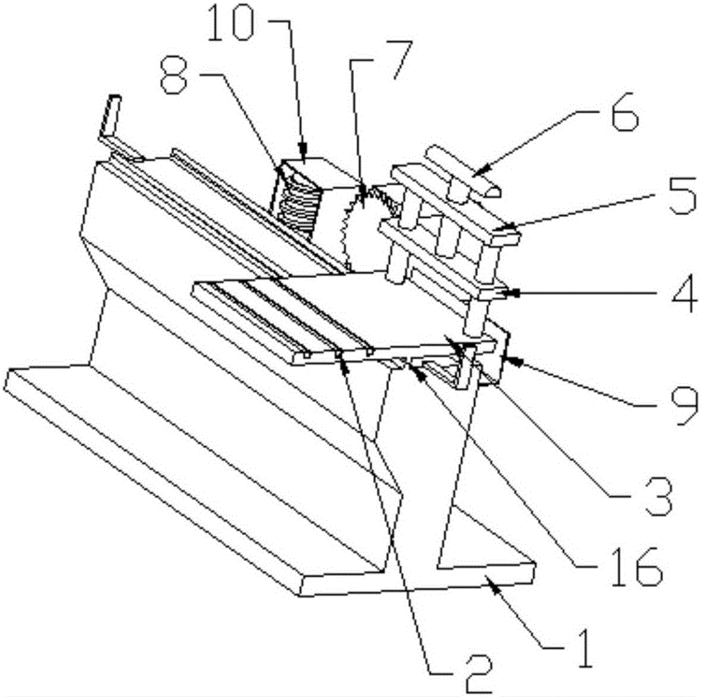
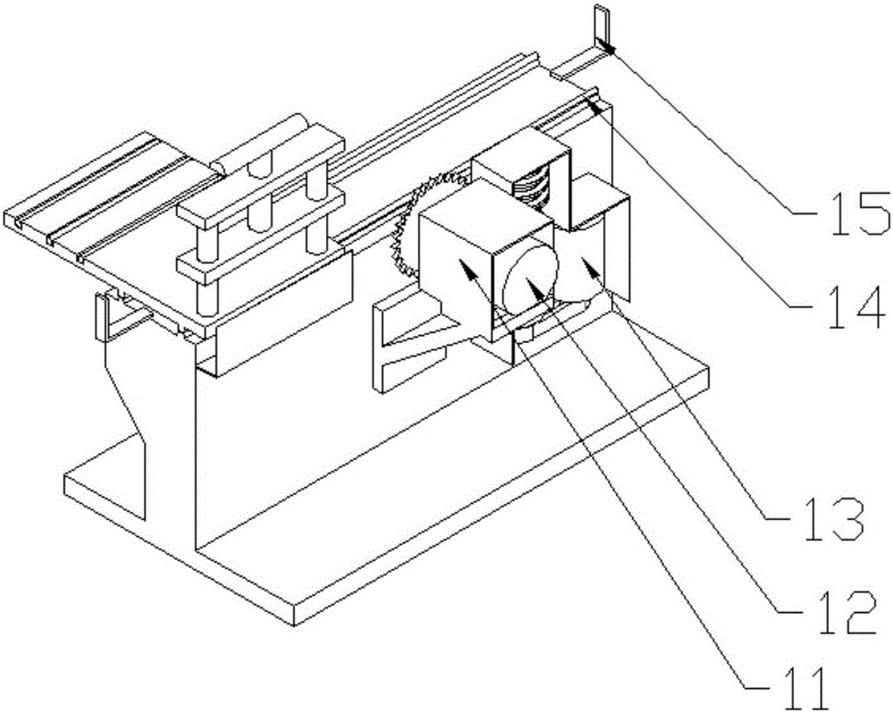
[0016] Such as figure 1 , figure 2 As shown, the present invention is a woodworking comb machine, including a base 1, an electric roller 2, a mobile table 3, a pressing plate 4, a fixed frame 5, a handle 6, a saw disc 7, a comb cutting tool 8, a baffle 9, An anti-dust safety cover 10, a motor shield 11, a first motor 12, a second motor 13, a guide rod 14, a limit plate 15 and a linear needle roller bearing 16.

[0017] A mobile platform 3 is arranged above the base 1. The mobile platform 3 is slidingly connected to the base 1. One end of the mobile platform 3 is aligned with one end of the longitudinal end face of the base 1. The mobile platform 3 can move along the longitudinal direction of the base 1. Above the mobile platform 3 An electric drum 2 is provided at one end of the base 1, and a saw disc 7 driven by a first motor 12 is provide...


PUM


Abstract

The invention provides a carpentry tooth slotting machine, which comprises a base, a moving platform, an electric roller, a saw disc, a tooth slotting cutting tool, a first motor and a second motor, wherein the moving platform is arranged above the base; the base is connected with the moving platform in a sliding way; one end of the moving platform is aligned with one end of the longitudinal end face of the base; one end above the moving platform is provided with the electric roller; one side, far away from the electric roller, of the base is provided with the saw disc which is driven by the first motor; the saw disc is located between the base and the first motor; the saw disc is vertical to the upper end face of the base; the same side of the base and the saw disc is also provided with the tooth slotting cutting tool which is driven by the second motor; and the center axis of the tooth slotting cutting tool is vertical to the upper end face of the base. The carpentry tooth slotting machine has the advantages that the structure is simple; the safety is high; and the production efficiency is greatly improved.

Description

technical field [0001] The invention belongs to the field of woodworking processing machinery, in particular to a woodworking comb machine. Background technique [0002] With the rapid development of the economy, people's awareness of environmental protection has been enhanced, and the utilization of wood has been strictly controlled. Excessive logging is strictly prohibited, and it is necessary to meet the needs of economic development and control product costs. In this market environment, It is necessary to improve the utilization rate of wood, to carry out secondary recycling of wood or to lengthen short wood, which is a mature technology at present, and combing machine and lengthening machine can be used together to lengthen short wood. Moreover, the strength and hardness of the lengthened wood planks are the same as those of the original long wood, which can meet the needs of processing and production. At present, the comb machines on the market are automated and equipp...

Claims


Application Information

Patent Timeline
Patent Type & Authority Applications(China)
IPC IPC(8): B27F1/12B27G19/02B27B5/02
Inventor 孙继宏
Owner TIANJIN XIANGYUAN FURNITURE CO LTD
Why Eureka
Try Eureka