
Electric driving bogie for subway engineering vehicle

A subway engineering vehicle, electric drive technology, applied in the direction of bogies, railway car body parts, transmission devices driven by electric motors, etc., can solve the problems of high cost of bogie configuration, difficulty in adding power equipment, and increase in manufacturing and maintenance costs, etc. Achieve the effect of increasing maximum operating speed, solving poor performance, and reducing manufacturing maintenance costs

Active Publication Date: 2015-12-16
CRRC SHANDONG CO LTD
View PDF6 Cites 7 Cited by
  • Summary
  • Abstract
  • Description
  • Claims
  • Application Information

AI Technical Summary

Problems solved by technology

[0003] For subway engineering vehicles, the existing two modes of bogies are not designed based on the needs of subway engineering vehicles.
The first type of bogie was originally designed for railway freight cars, but its problems are: loose structure and low running speed; it adopts the joint bearing of center plate and side bearing to transmit vertical force and traction force, and transmits longitudinal force, lever brake system and freight car bogie When the H frame is used for subway engineering vehicles with power requirements, it is difficult to add power equipment; the second type of bogie is expensive for various configurations, and its special interfaces for subway passenger cars, such as the first series of rotary arm positioning and the second series of air spring suspension, are very important for engineering. The vehicle puts forward high interface manufacturing requirements, which increases the difficulty of manufacturing and increases the cost of manufacturing and maintenance

Method used


Image

  • Electric driving bogie for subway engineering vehicle
  • Electric driving bogie for subway engineering vehicle
  • Electric driving bogie for subway engineering vehicle

Examples


Embodiment Construction

[0044] The present invention will be further described below in conjunction with the accompanying drawings and embodiments.

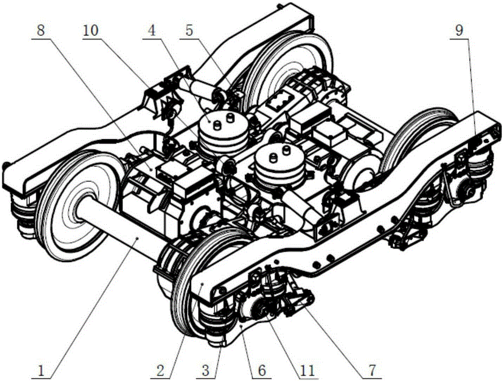
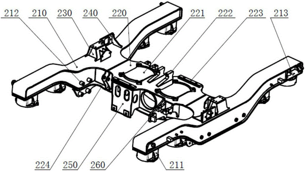
[0045] Such as figure 1As shown, the present invention includes two wheel pairs 1, a frame 2, four primary suspension systems 3, a secondary suspension system 4, a set of braking devices 5, four axle boxes 6, and a set of wheel pair connecting devices 7. One set of electric driving device 8, one set of weighing device 9, traction device 10, two grounding devices 11. The axle box 6 is installed at both ends of each wheel pair 1; the primary suspension system 3 is vertically installed between the axle box 6 and the frame 2; the secondary suspension system 4 is installed on the frame 2; The device 5 is installed inside the frame 2; the wheel pair connection device 7 is installed on the lower part of the axle box 6; the electric drive device 8 is installed on the wheel pair 1 and the frame 2; the weighing device 9 is installed at the end of the frame 2; T...


PUM


Abstract

The invention discloses an electric driving bogie for a subway engineering vehicle. The electric driving bogie comprises a framework, two pairs of wheel sets, an axle box, a plurality of primary suspension systems, a secondary suspension system, a driving device, a traction device, an axle box connecting device, a braking device, a weighing device and a grounding device. The electric driving bogie has the beneficial effects that problems such as center plate bearing and longitudinal impact of traction are solved by adopting a rubber-metal pad bearing plus traction rod traction pattern; by adopting a unit braking device for replacing a conventional lever braking device, the daily maintenance free is realized, and the maintenance amount is reduced; compared with the structure of a substrate coach bogie, the structure of the bogie is simple; the structural pattern of the bogie is optimized according to the requirements of the subway engineering vehicle; rubber-metal pad bearing is used for replacing air spring bearing and is supplemented by a device for preventing the side rolling of a vehicle body; a single traction rod is used for replacing a Z-shaped double traction rod and a center pin; an interface of the vehicle body and the structure of the bogie are simplified; and the manufacturing manufacturability is improved.

Description

technical field [0001] The invention relates to the railway vehicle bogie technology, in particular to an electric drive bogie for a subway engineering vehicle. Background technique [0002] With the continuous expansion of domestic subway scale, the demand for engineering vehicles for subway maintenance is also increasing. At present, there is no uniform standard for engineering vehicle bogies, and there are mainly two types of bogies. The first type adopts the reconstruction of the traditional truck bogie, which is connected with the car body through the center plate. The main systems of the bogie are all truck bogie types, such as the lever type brake shoe brake system, a series of Linol shock absorbers, etc.; The second type adopts the transformation of subway or passenger car bogie. Its main structure is the type of passenger car bogie, such as air springs, Z-shaped traction rods, and the positioning of the first series of pivoting arm axle boxes. [0003] For subway ...

Claims


Application Information

Patent Timeline
IPC IPC(8): B61F5/00B61F5/26B61F5/52B61C9/50
Inventor 杨文朋翟鹏军曲兆飞白文虽袁国庆罗林涛卞学谦刘明尚
Owner CRRC SHANDONG CO LTD
Learn More