Rail transit magnetic track brake provided with horizontal magnet exciting coils

A technology for magnetic rail brakes and excitation coils, which is applied in the direction of brakes, railway braking systems, and railway car body parts where the braking elements interact with the rails, etc. Shell wear, low braking efficiency of the excitation coil body, etc., to achieve the effect of ensuring good contact, improving reliability, and large braking force

Inactive Publication Date: 2015-12-16
CRRC QINGDAO SIFANG ROLLING STOCK RES INST
View PDF7 Cites 7 Cited by
  • Summary
  • Abstract
  • Description
  • Claims
  • Application Information

AI Technical Summary

Problems solved by technology

The excitation coil of the existing magnetic rail brake is usually arranged vertically relative to the rail surface, and the U-shaped iron core with the opening facing downward wraps the lower half of the excitation coil. The U-shaped iron core cannot completely cover the electromagnetic path of the upper half of the excitation coil.
The disadvantage of this structure is that a considerable proportion of the upper half of the magnetic flux generated by the excitation coil is closed in the air without passing through the iron core, resulting in the loss of electromagnetic force; because only the lower half of the excitation coil is wrapped inside the U-shaped iron core While being protected, the upper part of the excitation coil protected only by the thin excitation coil protective case is vulnerable to external damage; due to the inevitable gap between the iron core and the coil protection case, there will be a gap between the iron core and the coil during the driving of the vehicle. Frequent vibrations are generated, which increases the noise during the driving process of the vehicle and easily causes the iron core and the coil protection shell to collide with each other and wear excessively, which affects product reliability
[0003] Chinese Patent No. CN200580015726 discloses a magnetic track brake, specifically disclosing the following features: the brake electromagnet includes an excitation coil body and at least one longitudinally extending parallel to the excitation coil body, directly connected with the excitation coil body and used to connect the brake electromagnet The fixed slats fixed on other components of the magnetic track brake, the excitation coil body can move to maintain multiple magnetic joints, the excitation coil body is placed vertically, and a fixed slat is arranged on each side of the excitation coil body. That is, the excitation coil body is divided into an upper excitation coil and a lower excitation coil. Almost all the magnetic induction lines generated by the lower excitation coil pass through the iron core, while a considerable part of the magnetic induction lines generated by the upper excitation coil do not pass through the iron core. As a result, the upper excitation coil leaks. Magnetic flux, resulting in low braking efficiency of the entire field coil body

Method used


Image

  • Rail transit magnetic track brake provided with horizontal magnet exciting coils
  • Rail transit magnetic track brake provided with horizontal magnet exciting coils
  • Rail transit magnetic track brake provided with horizontal magnet exciting coils

Examples


Embodiment 1

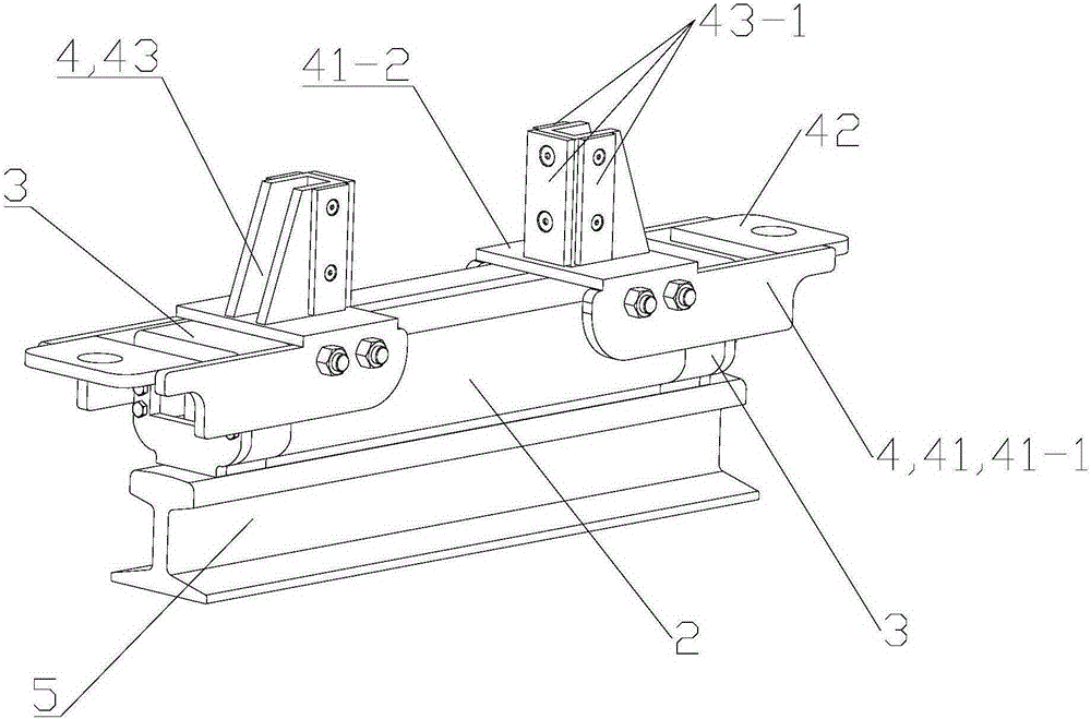
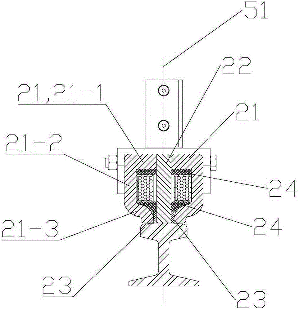
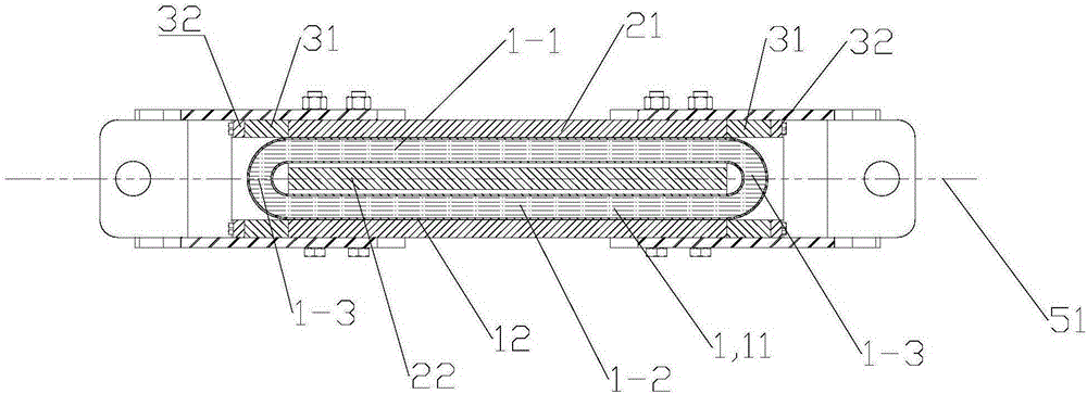
[0031] see attached figure 1 and attached image 3 The present invention discloses a rail transit magnetic track brake with a horizontally arranged excitation coil for rail transit vehicles, the magnetic rail brake includes an excitation coil assembly 1 , an iron core unit 2 , an end assembly 3 and a force transmission assembly 4 .

[0032] The excitation coil assembly 1 includes an excitation coil 11 and a coil protection case 12 , and the coil protection case 12 is wrapped around the periphery of the excitation coil 11 .

[0033] The excitation coil 11 is a group of coils composed of some winding coils. The excitation coil 11 has an elongated annular structure as a whole.

[0034] The coil protection shell 12 is a closed thin shell structure. The shape of the inner cavity of the coil protection shell 12 is completely consistent with the outer contour of the excitation coil 11. The excitation coil 11 is placed inside the coil protection shell 12 and completely wrapped by the...

Embodiment 2

[0045] The structural composition of the magnetic track brake of embodiment 2 is basically the same as that of the magnetic track brake of embodiment 1, and the distinguishing features are:

[0046] Each end assembly 3 includes an end cover 31 and a clearing board 32 , the outer contour shape of the end assembly 3 is consistent with the outer contour shape of the iron core unit 2 , and the middle part of the end assembly 3 is a hollow cavity. A gap is cut out on the lower end face of the end cover 31 to set up a clearing board 32. The clearing board 32 is made of elastic wear-resistant material and has the effect of an eraser. .

[0047] The two end assemblies 3 completely contain the circular arcs 1-3 at the front and rear ends of the excitation coil assembly 1 in the hollow cavity, and the two end assemblies 3 and the iron core unit 2 together form an inner cavity wrapping the excitation coil assembly 1 .

[0048] The lower end surface of the clearing plate 32 is in the sam...

Embodiment 3

[0050] The structural composition of the magnetic track brake of embodiment 3 is basically the same as that of the magnetic track brake of embodiment 1, and the distinguishing features are:

[0051] Each force transmission assembly 4 includes an iron core connection part 41 , a bogie connection plate 42 and a force transmission part 43 .

[0052] The iron core connecting part 41 is composed of two connecting plates 41-1 symmetrically arranged left and right with respect to the vertical surface 51 of the track. One. Connection through holes are provided at the positions corresponding to the bolt connection holes of the connecting plate 41 - 1 and the iron core unit 2 , and the connecting plates 41 - 1 on both sides are fixedly connected with the iron core unit 2 by bolts.

[0053] The bogie connecting plate 42 protrudes from the end of the transverse rib 41-2, and the left and right ends of the bogie connecting plate 42 are fixedly connected with the upper surface of the conne...


PUM


Abstract

The invention relates to a rail transit magnetic track brake provided with horizontal magnet exciting coils and applied to rail transit vehicles. A magnet exciting coil assembly of the magnetic track brake is transversely and horizontally arranged in an iron core unit. The magnet exciting coils are totally arranged in the iron core unit. The magnetic flux generated by the magnet exciting coil is almost completely closed in an iron core. Large brake force is provided by means of a few magnet exciting coils or low exciting current. The utilization rate of the magnetic flux of the magnet exciting coils is increased, and the conversion rate of brake force is increased. The magnet exciting coils are completely arranged in the iron core. Two end assemblies and the iron core unit form an inner cavity wrapping the magnet exciting coil assembly together, and it is guaranteed that the magnet exciting coils can be fully protected; and the reliability of the magnetic track brake is improved. When the rail transit magnet track brake acts, the lower end face of a barrier clearing plate is in contact with the upper end face of a track prior to the iron core unit, and foreign matter possibly existing on the surface of the track is removed; and it is guaranteed that pole shoes are in good contact with the surface of the track, and large brake force is obtained.

Description

technical field [0001] The present invention relates to the technical field of rail vehicle braking, in particular to a rail transit magnetic rail brake with a horizontally arranged excitation coil for rail transit vehicles. Background technique [0002] With the development of rail transit braking technology, magnetic rail brakes have been developed for many years as an important component of braking force output during emergency braking of vehicles. The excitation coil of the existing magnetic rail brake is usually arranged vertically relative to the rail surface, and the U-shaped iron core with the opening facing down wraps the lower half of the excitation coil, and the U-shaped iron core cannot completely cover the electromagnetic path of the upper half of the excitation coil. The disadvantage of this structure is that a considerable proportion of the upper half of the magnetic flux generated by the excitation coil is closed in the air and does not pass through the iron ...

Claims


Application Information

Patent Timeline
Patent Type & Authority Applications(China)
IPC IPC(8): B61H7/08
Inventor 王明星李家宝牛玉国崔雷张笑慰
Owner CRRC QINGDAO SIFANG ROLLING STOCK RES INST
Why Eureka
Try Eureka