Vehicle-mounted telescopic belt conveyor

A telescopic belt conveyor and vehicle-mounted technology, which is applied in the direction of conveyors, steering mechanisms, vehicle components, etc., can solve problems such as reducing the service life of tires and axles, slipping wheels, and large internal forces, so as to improve construction efficiency and flexibility Sexuality and easy operation

Active Publication Date: 2017-10-13
CHINA RAILWAY ENG MASCH RES & DESIGN INST CO LTD
View PDF9 Cites 0 Cited by
  • Summary
  • Abstract
  • Description
  • Claims
  • Application Information

AI Technical Summary

Problems solved by technology

Neither the modification of heavy trucks nor off-road vehicle cranes can improve the flexibility of running on narrow roads when the whole machine is walking
Compared with the traditional telescopic tire belt machine heavy truck or off-road vehicle suspension chassis, they all steer at the front, and other wheel sets do not participate in the steering, which mainly leads to excessive turning radius, the same turning angle of the inner and outer tires when turning, and rear The non-participation of the tires in the steering will lead to uneven wear of the tires, and it will also cause the axle to bear a large internal force when turning, which will reduce the service life of the tires and the axle; On the road, each wheel set bears uneven load, which will cause the wheel set to slip and make the whole vehicle equipment unable to travel in severe cases
[0003] When the existing telescopic belt conveyor is walking, the walking direction of the equipment can only be changed by operating the steering wheel located at the front of the car body, while the rear wheel set is a fixed wheel, which causes the turning radius of the equipment to be too large. Part of the ultra-long boom will also cause the inconvenience of turning the whole machine

Method used


Image

  • Vehicle-mounted telescopic belt conveyor
  • Vehicle-mounted telescopic belt conveyor
  • Vehicle-mounted telescopic belt conveyor

Examples


Embodiment Construction

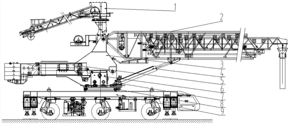
[0034] see figure 1 , shows the vehicle-mounted retractable belt conveyor of the present invention.

[0035] The vehicle-mounted telescopic belt conveyor includes a driving chassis 9 and an operating system arranged on the driving chassis, the operating system includes a feeding system 1, a cloth boom 2 and a rotary turntable 3, and the rotary turntable 3 passes through A slewing support 8 is installed and fixed on the driving chassis 9, a feeding system 1 is set on the rotary table 3, and the feeding system 1 includes a feeding belt and a feeding hopper, and the feeding hopper is located on the feeding One side of the belt is used to lower the conveyed materials. One end of the feeding system is connected to the top of the rotary table 3 through a pin shaft, and the other end can be placed on the ground through universal wheels. The distribution arm 2 is Truss structure, the cloth boom 2 includes a base arm, an intermediate arm and a forearm that expand and contract in seque...


PUM


Abstract

A vehicle-mounted extensible belt conveyor comprises a driving chassis and an operating system arranged on the driving chassis. The driving chassis comprises a vehicle frame; a cab is arranged at one end of the vehicle frame; the front portion, the middle and the rear portion of the lower end of the vehicle frame are each provided with an all-wheel steering wheel set which can rotate within 360 degrees; each all-wheel steering wheel set comprises a rotary supporting flange, a worm wheel and worm rotary assembly and a wheel set supporting structure assembly; each rotary supporting flange is fixed to the lower surface of a box girder of the vehicle frame; each worm wheel and worm rotary assembly is arranged at the lower end of the corresponding rotary supporting flange; each wheel set supporting structure assembly is arranged at the lower end of the corresponding worm wheel and worm rotary assembly. In this way, the vehicle-mounted extensible belt conveyor is controlled through different rotation angles of the all-wheel steering wheel sets, the flexibility of equipment and construction efficiency are improved, various steering modes are achieved, the vehicle-mounted extensible belt conveyor can adapt to different working conditions and construction environments, and unique novelty is achieved.

Description

technical field [0001] The invention relates to a vehicle-mounted telescopic belt conveyor. Background technique [0002] At present, almost all the telescopic belt conveyor chassis at home and abroad are heavy-duty trucks or off-road vehicle suspension chassis, and the slewing support is installed to connect the upper belt conveyor through technical transformation. Whether it is the transformation of heavy trucks or off-road vehicle cranes, it cannot improve the flexibility of running on narrow roads when the whole machine is walking. Compared with the traditional telescopic tire belt machine heavy truck or off-road vehicle suspension chassis, they all steer at the front, and other wheel sets do not participate in the steering, which mainly leads to excessive turning radius, the same turning angle of the inner and outer tires when turning, and rear The non-participation of the tires in the steering will lead to uneven wear of the tires, and it will also cause the axle to b...

Claims


Application Information

Patent Timeline
Patent Type & Authority Patents(China)
IPC IPC(8): B65G15/00B65G47/18B65G21/14B62D7/14
Inventor 陆持禹欧阳博涵陈扬程凤张硕陈国瑞李玮吴春慧苏杰
Owner CHINA RAILWAY ENG MASCH RES & DESIGN INST CO LTD
Why Eureka
Try Eureka