Disassembly method of optical crystal assembly based on cantilever

A technology of optical crystal and disassembly method, which is applied to cranes and other directions, can solve problems such as complicated lifting operations, and achieve the effects of compact structure, convenient and reliable lifting, and flexible movement

Active Publication Date: 2017-06-20
HARBIN INST OF TECH
View PDF8 Cites 0 Cited by
  • Summary
  • Abstract
  • Description
  • Claims
  • Application Information

AI Technical Summary

Problems solved by technology

[0003] In order to solve the problem of complex hoisting operation of the optical crystal assembly in the complex environment of the existing laser range, the present invention further proposes a cantilever-based disassembly method for the optical crystal assembly

Method used


Image

  • Disassembly method of optical crystal assembly based on cantilever
  • Disassembly method of optical crystal assembly based on cantilever
  • Disassembly method of optical crystal assembly based on cantilever

Examples


specific Embodiment approach 1

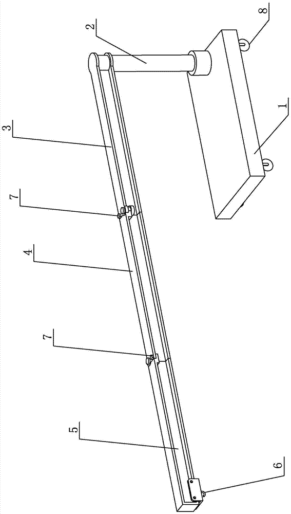
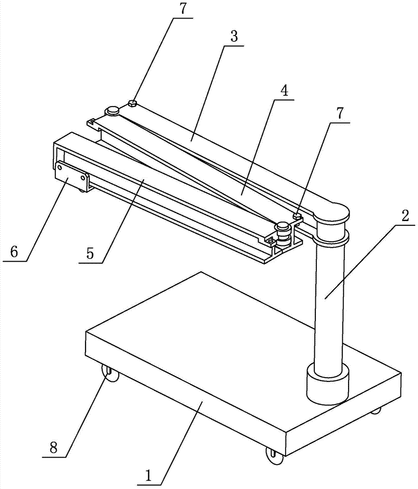
[0007] Specific implementation mode one: combine figure 1 and figure 2 Describe this embodiment, the disassembly method of the cantilever-based optical crystal assembly described in this embodiment includes a base 1, a column 2, a first cantilever 3, a middle cantilever 4, an end cantilever 5 and a hook 6, and the base 1 is horizontally arranged The rectangular plate body, the column 2 is vertically installed on the upper surface of one end of the base 1, one end of the first section of the cantilever 3 is connected to the upper end of the column 2, the other end of the first section of the cantilever 3 is rotationally connected with one end of the middle cantilever 4, and the middle cantilever The other end of 4 is connected with one end of the end cantilever 5, and the other end of the end cantilever 5 is provided with a hook 6.

specific Embodiment approach 2

[0008] Specific implementation mode two: combination figure 1 and figure 2 To illustrate this embodiment, the disassembly method of the cantilever-based optical crystal assembly described in this embodiment also includes two locking bolts 7, and the other end of the first cantilever 3 is connected to one end of the middle cantilever 4 through a locking bolt 7 , the other end of the middle cantilever 4 is connected with one end of the end cantilever 5 through a locking bolt 7 . Other components and connections are the same as those in the first embodiment.

specific Embodiment approach 3

[0009] Specific implementation mode three: combination figure 1 and figure 2 To illustrate this embodiment, four moving rollers 8 are arranged on the lower surface of the base 1 based on the method of disassembling and assembling the cantilever optical crystal assembly in this embodiment, and the four moving rollers 8 are arranged in a rectangular shape. Other compositions and connections are the same as those in Embodiment 1 or 2.

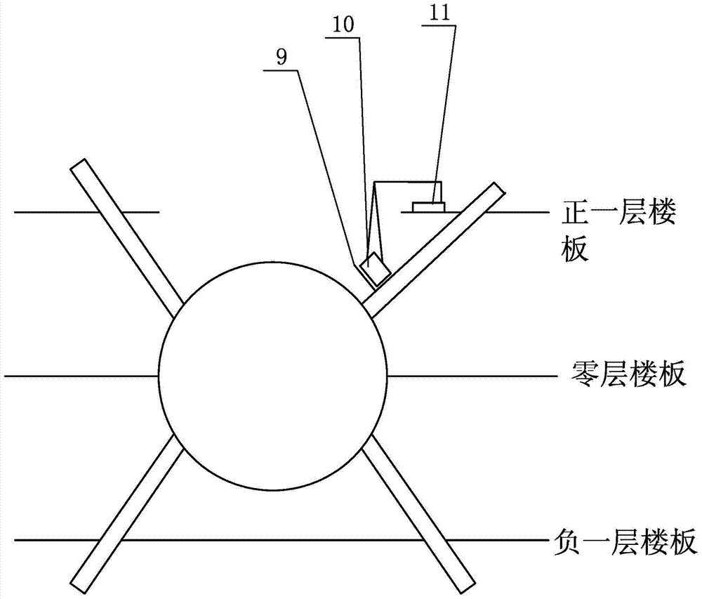
[0010] combine image 3 and Figure 4 Describe the installation steps of optical crystal components:

[0011] Step 1. The first cantilever 3, the middle cantilever 4, and the end cantilever 5 of the present invention are folded, and the cantilever disassembly system 11, the support frame 9, and the clean box 10 are transported to the shooting range, and installed on the first floor of the shooting range. location;

[0012] Step 2, unfold the first cantilever 3, the middle cantilever 4, and the end cantilever 5, respectively insert the lockin...


PUM


Abstract

The invention relates to a disassembly and assembly system for optical crystal components, in particular to a cantilever-type disassembly and assembly system for optical crystal components and aims to solve the problem of complicated hoisting operation of the optical crystal components in the conventional laser range complicated environments. The disassembly and assembly system comprises a base, an upright post, a first section cantilever, an intermediate cantilever, a tail end cantilever and a lifting hook, wherein the base is a horizontally arranged rectangular plate body; the upright post is vertically mounted on the upper surface of one end of the base; one end of the first section cantilever is connected with the upper end of the upright post; the other end of the first section cantilever is in rotational connection with one end of the intermediate cantilever; the other end of the intermediate cantilever is connected with one end of the tail end cantilever; and the lifting hook is arranged at the other end of the tail end cantilever. The disassembly and assembly system belongs to the field of optical instruments.

Description

technical field [0001] The invention relates to a method for disassembling and assembling an optical crystal component, in particular to a method for disassembling and assembling an optical crystal component based on a cantilever type, and belongs to the field of optical instruments Background technique [0002] The Shenguang III project under construction in my country is a key project of the national inertial confinement laser fusion project. The project requires a large number of optical components, which are called online replaceable units LRU. These optical components need to be disassembled and replaced online after the components are damaged. The optical element and the mechanical frame parts holding the optical element form a special optical crystal assembly. During the assembly and disassembly process of the optical crystal assembly, due to the large size and heavy weight of the assembly, an auxiliary hoisting system is required. However, the working environment o...

Claims


Application Information

Patent Timeline
IPC IPC(8): B66C23/04B66C23/16B66C23/62B66C23/687
Inventor 白清顺卢礼华王灿滨陈家轩张庆春赵航
Owner HARBIN INST OF TECH
Why Eureka
Try Eureka