A far-infrared heating chlorine dioxide generator

A chlorine dioxide and far-infrared technology, applied in chlorine oxide and other directions, can solve the problems of reduced reliability and safety of generators, hindered gas phase removal of chlorine dioxide, complicated manufacturing and control, etc. The effect of improving the performance and reducing the processing cost

Active Publication Date: 2017-07-11
SHENZHEN OUTAIHUA ENG EQUIP
View PDF4 Cites 0 Cited by
  • Summary
  • Abstract
  • Description
  • Claims
  • Application Information

AI Technical Summary

Problems solved by technology

This structural method not only has multiple heaters with high power consumption, complex manufacturing and control, but also has defects such as material pipe Louis blockage and chlorine dioxide gas phase removal being blocked in the series connection method. Since chlorine dioxide is explosive, when the pipeline blockage is serious, it will Lead to the occurrence of safety accidents of chlorine dioxide generators, greatly reducing the reliability and safety of the generators

Method used


Image

  • A far-infrared heating chlorine dioxide generator
  • A far-infrared heating chlorine dioxide generator
  • A far-infrared heating chlorine dioxide generator

Examples


example 1

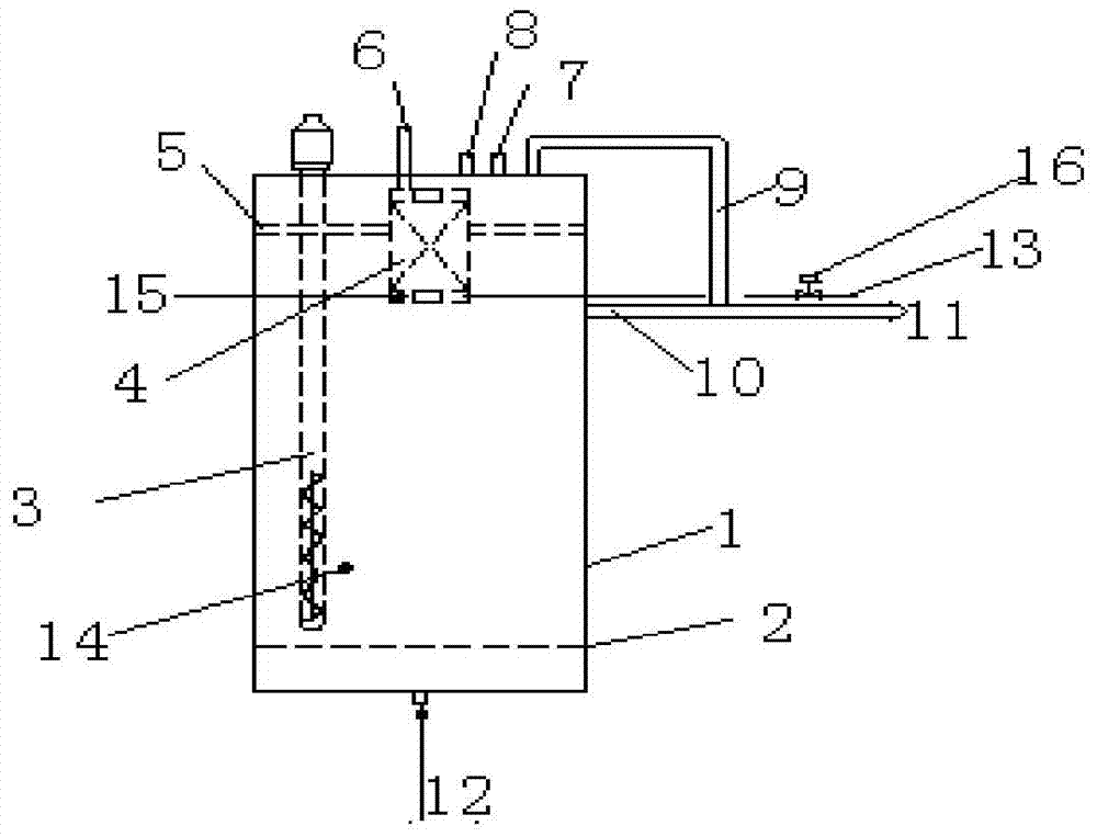
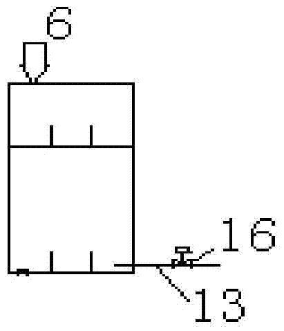
[0034] Such as figure 1 with image 3 As shown, a far-infrared heating chlorine dioxide generator of the present invention includes a main reactor 1, an aeration pan 2, a far-infrared quartz heater 3, a low-temperature reactor 4, a support frame 5, a raw material feeding pipe 6, an outlet Air pipe 9, liquid outlet pipe 10, suction pipe 11, aeration pipe 12 and air conditioning pipe 13; top and goes deep into the reactor 1, the low temperature reactor 4 is installed inside the main reactor 1, and is fixed on the inner upper part of the main reactor 1 by the support frame 5, and the raw material feed pipe 6 passes through after the top of the main reactor 1 It is connected with the top of the cryogenic reactor 4, the outlet pipe 9 is arranged on the top of the main reactor 1, the liquid outlet pipe 10 is arranged on the top of the main reactor 1 and extends into the inside of the main reactor 1, and the suction pipe 11 is respectively It communicates with the gas outlet pipe 9...

example 2

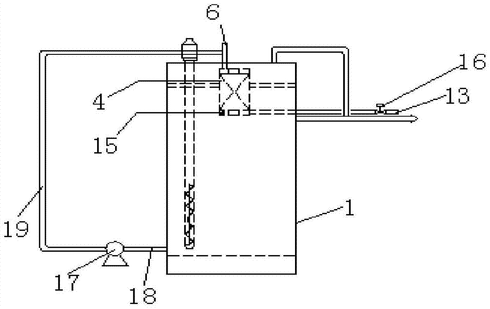
[0040] This example is basically the same as Example 1, the difference is, such as figure 2 with image 3 As shown, the main reactor 1 in this example is also provided with a mother liquor circulation system connected with the low temperature reactor 4 . This circulation system comprises mother liquid circulating pump 17, and the feeding port of mother liquid circulating pump 17 is communicated with the bottom of main reactor 1 by mother liquid discharge pipe 18, and the discharge port of mother liquid circulating pump 17 is fed into raw material by mother liquid feeding pipe 19. The feed pipe 6 is connected. When the circulation system is in operation, the mother liquor in the main reactor 1 enters the low-temperature reactor 4 after passing through the mother liquor discharge pipe 18, the mother liquor circulation pump 17 and the mother liquor feed pipe 19 and the raw material feed pipe 6 successively. On the one hand, the incompletely reacted raw materials in a part of t...


PUM

PropertyMeasurementUnit
pore sizeaaaaaaaaaa

Abstract

The invention discloses a far-infrared heating chlorine dioxide generator, comprising a main reactor (1), an aeration pan (2), a far-infrared quartz heater (3), a low temperature reactor (4), a raw material feeding A pipe (6), an air outlet pipe (9), a liquid outlet pipe (10), a suction pipe (11), an aeration pipe (12) and an air conditioning pipe (13); the aeration plate (2) is arranged at the In the lower part of the interior of the main reactor (1), the far-infrared quartz heater (3) is fixed on the top of the main reactor (1) and penetrates deep into the main reactor (1). The far-infrared heating chlorine dioxide generator of the present invention not only greatly improves the raw material conversion rate of the generator, significantly reduces power consumption, is safer and more reliable, but also greatly simplifies the overall structure, significantly reduces the manufacturing cost, and is conducive to the generation of chlorine dioxide. It is widely used in the field of water treatment.

Description

technical field [0001] The invention relates to the field of chemical machinery, in particular to a far-infrared heating chlorine dioxide generator. Background technique [0002] Chlorine dioxide is an excellent fungicide, high-efficiency bleach and strong oxidant recognized by the International Health Organization. It has been applied and promoted in the field of water treatment in my country for more than 20 years. At present, it has become the mainstream agent for sterilization and disinfection, algae deodorization, decolorization and degradation in water treatment process. [0003] Chlorine dioxide generator is a special equipment for preparing chlorine dioxide. In most chemical preparation processes with chlorate as the main raw material, in order to meet the endothermic reaction conditions, it is necessary to provide enough heat for the chemical reaction to ensure that the reaction is complete and complete, the conversion rate of raw materials is the highest, and the ...

Claims


Application Information

Patent Timeline
Patent Type & Authority Patents(China)
IPC IPC(8): C01B11/02
Inventor 崔永顺邵强孙玉卫志兵王锋曾妍
Owner SHENZHEN OUTAIHUA ENG EQUIP
Why Eureka
Try Eureka