
Continuous feeding device for solution method centrifugal spinning

A technology of centrifugal spinning and feeding device, which is applied in the directions of feeding solution to spinnerets, textile and papermaking, filament/thread forming, etc. problem, to achieve the effect of low cost investment, small space occupation, and simple structure

Inactive Publication Date: 2015-12-16
ZHEJIANG SCI-TECH UNIV
View PDF6 Cites 10 Cited by
  • Summary
  • Abstract
  • Description
  • Claims
  • Application Information

AI Technical Summary

Problems solved by technology

In actual use, it is found that the above two types of centrifugal spinning spinnerets or horizontal disks are all stored and supplied by the storage chamber. Since the spinneret is always in a state of high-speed rotation, the spinning It is difficult for the liquid to be continuously and stably transported into the storage chamber, that is, the difficulty of continuous feeding is relatively large. Every time the spinning liquid is added, it needs to be stopped for processing, which seriously affects the process of mass production.

Method used

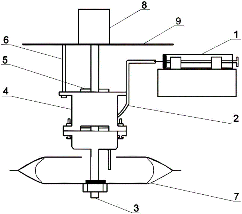
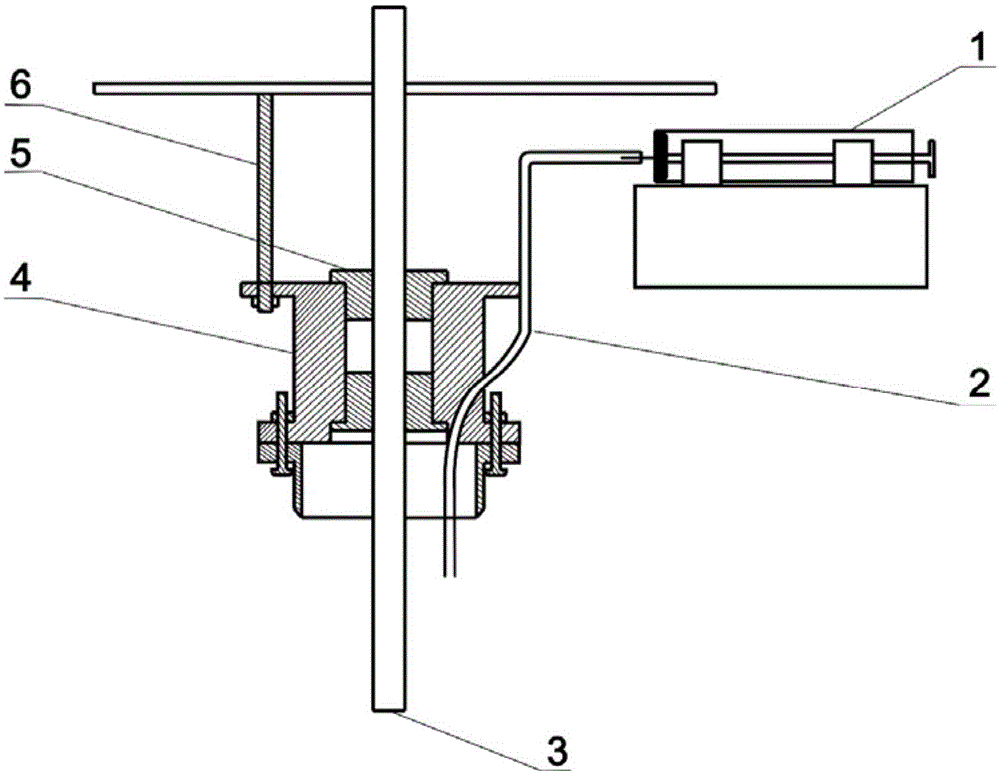

Image

  • Continuous feeding device for solution method centrifugal spinning
  • Continuous feeding device for solution method centrifugal spinning
  • Continuous feeding device for solution method centrifugal spinning

Examples


Embodiment Construction

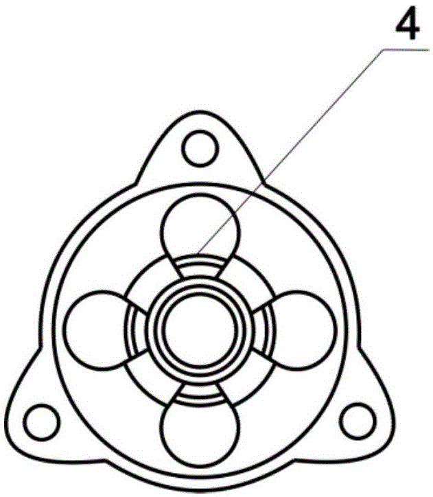
[0016] Such as Figure 1-3 As shown, the continuous feeding device suitable for solution centrifugal spinning includes a motor 8 and a spinneret 7, the motor 8 is arranged on the frame 9, one end of the transmission shaft 3 is connected to the motor 8, and the other end is connected to the spinneret 7 Connect; the hose holder 4 is fixed on the frame 9 through the support rod 6, the inside of the hose holder 4 has a longitudinal through hole, and the two ends of the through hole are in the shape of counterbore; the two ends of the through hole are respectively provided with a bearing 5 , The cross section of the two bearings 5 ​​is in the shape of a boss, matching with the shape of the counterbore at both ends of the through hole. The transmission shaft 3 is installed in the bearing 5 and coincides with the center line of the through hole; a rubber hose 2 passes through the oblique through hole located at the side of the hose holder 4, and the feed port of the rubber hose 2 is ...


PUM


Abstract

The invention relates to the field of centrifugal spinning, and aims to provide a continuous feeding device for solution method centrifugal spinning. The device comprises a motor, a spinning jet and a hose fixing base. The motor is arranged on a rack. One end of a transmission shaft is connected to the motor, and the other end of the transmission shaft is connected with the spinning jet. The hose fixing base is fixed to the rack through a supporting rod, and a longitudinal through hole is formed in the hose fixing base. Two bearings are arranged at the two ends of the through hole respectively. The transmission shaft is installed in a flange bearing and coincides with the center line of the through hole. A rubber hose penetrates through an inclined through hole formed in one side of the hose fixing base, a feeding port of the rubber hose is connected to an outlet of an injection pump, and a discharging port of the rubber hose stretches into a cavity of the spinning jet in a suspended mode without making contact with the inner wall of the cavity or the transmission shaft. The continuous feeding device can feed a spinning solution to the spinning jet or a horizontal disc continuously, and therefore the situation that the development of solution method centrifugal spinning is limited by feeding difficulty will not occur. The continuous feeding device is simple in structure, small in occupied space, low in cost, high in adaptability, capable of improving production efficiency and suitable for batch production.

Description

technical field [0001] The invention belongs to the field of centrifugal spinning, and in particular relates to a continuous feeding device suitable for solution centrifugal spinning. Background technique [0002] In recent years, researchers have paid attention to a simple and efficient method for preparing nanofibers in the mass production of nanofibers——centrifugal spinning method. Its spinning output, spinnable material types and fiber orientation There are significant advantages in terms of arrangement degree and so on. [0003] There are two main forms of existing centrifugal spinning, one is that the spinneret rotates at high speed, and the solution or melt is extruded through the nozzle to generate a jet, which is condensed and broken in the air to form fibers; the other is that the horizontal disc rotates at high speed. Rotating, the film flattened on the disc gradually becomes thinner until it breaks under the action of centrifugal force, forming filaments and con...

Claims


Application Information

Patent Timeline
Patent Type & Authority Applications(China)
IPC IPC(8): D01D1/06D01D5/18
Inventor 杨斌陈欢欢刘晨李祥龙侯腾
Owner ZHEJIANG SCI-TECH UNIV
Learn More