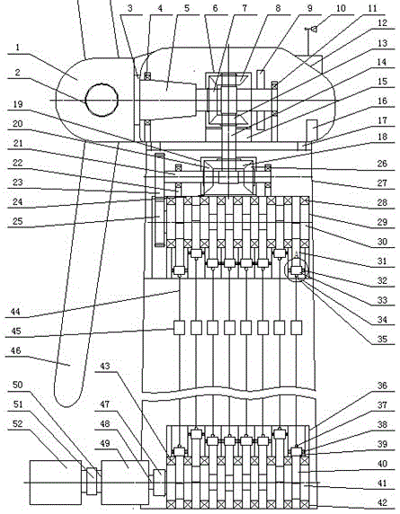
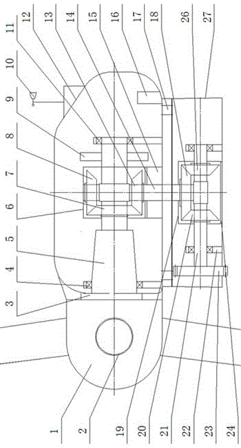
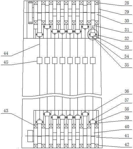
[0013] Such as figure 1 As shown, the present invention is a high-power flexible long-distance transmission device for wind power generation, in particular, the use of a crank-slider-cable mechanism to realize the flexible long-distance transmission of mechanical energy of the wind power transmission system, including the wind wheel, the main shaft 5, the nacelle 12, and the first stage Speed increaser, tower 27, crank-slider-cable mechanism, second-stage speed increaser 49 and generator 52. The wind wheel is composed of three blades 46 and a hub 1. The blades 46 are mounted by flanges On the hub 1; a pitch device 2 is installed in the hub 1, and the pitch device 2 is connected with the blade 46. The rear flange 3 of the hub 1 and the main shaft 5 are fixedly connected by bolts, and the main shaft 5 passes through the main bearing seat 4 and the rear bearing The seat 11 is fixed on the bottom plate of the nacelle 12, and a mechanical brake device 9 is installed at the rear end of the main shaft 5;
[0014] The nacelle 12 of the wind turbine is installed on the tower 27 through a yaw bearing 17, a counterweight 16 is installed at the inner rear end of the nacelle 12, and an anemometer 10 is installed at the top and rear end of the nacelle 12.
[0015] Such as figure 1 , figure 2 , image 3 As shown, the first-stage speed increaser includes a first set of gearboxes 6 and a second set of gearboxes 19. The first set of gearboxes 6 are mounted on the elastic shock absorber 15 at the bottom of the nacelle, and the first set of gearboxes 6 is equipped with a first large bevel gear 7 and a first small bevel gear 8 and a second small bevel gear 13, the first large bevel gear 7 is fixedly connected to the main shaft 5, and the first large bevel gear 7 and the first small bevel gear 8 are respectively It meshes with the second pinion bevel gear 13. The first pinion bevel gear 8 and the second pinion bevel gear 13 are respectively fixedly mounted on the vertical shaft 14. The lower end of the vertical shaft 14 is connected to the second large bevel gear box 19 in the second group. The bevel gear 18 is connected. The second set of gearbox 19 is fixedly mounted on the elastic shock absorber 24 on the upper case 29. The second set of gearbox 19 is equipped with the second large bevel gear 18 and the third small bevel gear 20 and the first Four small bevel gears 26, the second large bevel gear 18 is fixedly installed at the end of the vertical shaft 14, the second large bevel gear 18 meshes with the third small bevel gear 20 and the fourth small bevel gear 26, and the third small bevel gear 20 and the fourth pinion gear 26 are respectively fixedly installed on the horizontal shaft 21. The horizontal shaft 21 is supported by a pair of bearings and installed on a pair of bearing seats 22. The end of the horizontal shaft 21 is equipped with a first spur gear 23. The gear 23 meshes with a second spur gear 25 fixedly mounted on the upper crankshaft 30, and the second spur gear 25 is axially fixedly mounted on the input end of the upper crankshaft 30.
[0016] Such as figure 1 , figure 2 , image 3 , Figure 4 , Figure 5 , Image 6 , Figure 7 , Picture 8 As shown, the crank-slider-cable mechanism includes an upper crankshaft 30, an upper connecting rod 31, an upper sliding block 33, an upper lifting ring 34, a lower crankshaft 41, a lower connecting rod 40, a lower sliding block 39, and a lower lifting ring 37. , The steel cable 44 and the tensioning device 45; wherein the upper crankshaft 30 is axially fixedly installed in the upper case 29 and the lower case 35 at the upper end of the tower 27 by several pairs of tapered roller bearings 28, the big end bearing bush of the upper connecting rod 31 Connected with the connecting rod journal of the upper crankshaft 30, the small head bearing bush is connected with the pin of the upper sliding block 33, and one or two pairs of first rolling bearings 32 are installed on the upper sliding block 33 to facilitate the installation of the lower box on the top of the tower 27 The upper guide groove opened in 35 slides smoothly up and down. The upper lifting ring 34 is installed on the upper sliding block 33. The upper lifting ring 34 is connected to the steel cable 44. The tensioning device 45 for the tension of the steel cable, the other end of the steel cable 44 It is fixedly connected with the lower lifting ring 37, the lower lifting ring 37 is fixedly installed on the lower sliding block 39, and one or two pairs of second rolling bearings 38 are installed on the lower sliding block 39 to facilitate the opening of the lower guide inside the upper box 36 at the bottom of the tower 27 The groove slides smoothly up and down. The lower sliding block 39 is connected to the small end bearing bush of the lower connecting rod 40 through a pin. The big end bearing bush of the lower connecting rod 40 is connected to the connecting rod journal of the lower crankshaft 41. The lower crankshaft 41 is composed of several pairs of tapered rollers. The sub-bearing 43 is axially fixedly installed in the upper box 36 and the lower box 42 at the bottom of the tower 27.
[0017] The output end of the lower crankshaft 41 is connected through the first coupling 47 and the input shaft 48 of the second-stage speed increaser 49.
[0018] The output shaft 50 of the second-stage speed increaser 49 is connected to the generator 52 through a second coupling 51.
[0019] The present invention will be described in detail below in conjunction with embodiments and drawings.
[0020] The high-power flexible long-distance transmission device for wind power generation according to Figure 1, including: wind wheel, main shaft 5, nacelle 12, first-stage speed increaser, tower 27, crank-slider-cable mechanism, second-stage speed increase 器49和generator 52. The wind wheel is composed of three blades 46 and the hub 1. The blades 46 are mounted on the hub 1 through flanges. The pitch device 2 is installed in the hub 1. The pitch device 2 is connected to the blades 46, and the pitch device is 2 pairs. The blade 46 is controlled. The blade 46 makes a circular motion around the hub 1 under the action of the pitch device 2. Under different wind speed conditions, the pitch device 2 finds the best angle of attack by changing the inlet angle of the blades. Improve the utilization of wind energy. At the same time, under extreme storm conditions, the pitch device 2 makes the blade 46 perpendicular to the wind, with the smallest windward area; the rear flange 3 of the hub 1 and the main shaft 5 are fixedly connected by bolts, and the main shaft 5 passes through the main bearing seat 4 and the rear bearing seat 11 are fixed on the bottom plate of the nacelle 12. The end of the main shaft 5 is equipped with a mechanical brake device 9. The mechanical brake device 9 is often used in conjunction with the pitch device 2. Adjust the pitch first to reduce the speed of the wind wheel, and then Braking in order to reduce the braking load and reduce the impact on the first set of bevel gearbox 6;
[0021] The nacelle 12 of the wind turbine is installed on the upper tower 27 through a yaw bearing 17 to realize the wind resistance function; the inner rear end of the nacelle 12 is equipped with a counterweight 16 to achieve the force balance of the entire nacelle; the nacelle 12 An anemometer 10 is installed at the top and rear to realize real-time monitoring of wind direction changes; the first-stage speed increaser includes two sets of gearboxes, the first set of gearboxes 6 are installed in the nacelle, and the second set of gearboxes 19 are installed on the tower. 27, the main function is to increase the speed and turn the rotating mechanical energy generated by the wind wheel; the crank-slider-cable mechanism is installed in the tower to realize the long-distance transmission of the rotating mechanical energy generated by the wind wheel; the second-stage speed increaser 49 and generator 52 are placed on the ground, and the rotating mechanical energy transferred to the ground is accelerated by the second-stage speed increaser and then transferred to the generator for power generation. The specific implementation scheme is as follows: wind energy drives the blade 46 to move, and the motion of the blade 46 drives the main shaft 5 to rotate, converting wind energy into mechanical energy. The rotational motion of the main shaft 5 is increased and turned by the first-stage speed increaser to turn the blade 46 The generated rotational torque is transmitted to the upper crankshaft 30, which drives the upper crankshaft 30 to make a rotational movement. The rotational movement of the upper crankshaft 30 drives the upper slider 33 to perform vertical reciprocating movement through the transmission of the upper connecting rod 31, and the upper slider 33 vertically reciprocates. The movement is transmitted to the lower sliding block 39 through the steel cable 44, which drives the lower sliding block 39 to make a vertical reciprocating movement. The vertical reciprocating movement of the lower sliding block 39 drives the lower crankshaft 41 to rotate through the transmission of the lower connecting rod 40, and the lower crankshaft 41 The rotational motion of φ is transmitted to the second-stage speed increaser 49 through the output end, and after the speed is increased by the second-stage speed increaser 49, it is transmitted to the generator 52 through the output shaft, so that mechanical energy is converted into electrical energy, and finally connected to the transmission grid;
[0022] The first-stage speed increaser includes a first set of gearboxes 6 and a second set of gearboxes 19. The first set of gearboxes 6 are installed on the elastic shock absorber 15 at the bottom of the nacelle. The main function of the elastic shock absorber 15 is It reduces the vibration transmitted from the main shaft 5 to the first set of gearboxes 6. The first set of gearboxes 6 are equipped with a first large bevel gear 7 and a first small bevel gear 8 and a second small bevel gear 13, the first large bevel gear 7 is fixedly connected to the main shaft 5, the first large bevel gear 7 meshes with the first small bevel gear 8 and the second small bevel gear 13 respectively, the first small bevel gear 8 and the second small bevel gear 13 are respectively fixedly installed on the vertical shaft 14, in order to reduce the impact load and uneven load distribution during the transmission process, the first small bevel gear 8 and the second small bevel gear 13 are symmetrically arranged on both sides of the first large bevel gear 7 to achieve a balance of force transmission, vertical The lower end of the shaft 14 is connected with the second large bevel gear 18 in the second set of gearbox 19, the second set of gearbox 19 is fixedly installed on the elastic shock absorber 24 on the upper case 29, the elastic shock absorber 24 is mainly The function is to reduce the vibration transmitted from the first set of gearboxes 6 to the second set of gearboxes 19. The structure of the second set of gearboxes 19 is similar to that of the first set of gearboxes 6. The second set of gearboxes 19 are equipped with The second large bevel gear 18 and the third small bevel gear 20 and the fourth small bevel gear 26, the second large bevel gear 18 is fixedly installed at the end of the vertical shaft 14, the second large bevel gear 18 and the third small bevel gear 20 and The fourth pinion bevel gear 26 meshes, the third pinion bevel gear 20 and the fourth pinion bevel gear 26 are respectively fixedly mounted on the horizontal shaft 21. The horizontal shaft 21 is supported by a pair of bearings and mounted on a pair of bearing seats 22. The horizontal shaft A first spur gear 23 is installed at the end of 21. The first spur gear 23 meshes with a second spur gear 25 fixedly installed on the upper crankshaft 30, and the second spur gear 25 is fixedly installed on the input end of the upper crankshaft 30; After the gearbox accelerates and steers the rotational power generated by the wind wheel, it is transmitted to the upper crankshaft 30 through the first spur gear 23 and the second spur gear 25, and drives the upper crankshaft 30 to rotate;
[0023] The crank-slider-cable mechanism includes an upper crankshaft 30, an upper connecting rod 31, an upper sliding block 33, an upper lifting ring 34, a lower crankshaft 41, a lower connecting rod 40, a lower sliding block 39, a lower lifting ring 37, and a steel cable. 44 and a tensioning device 45; wherein the upper crankshaft 30 is axially fixedly installed in the upper case 29 and the lower case 35 at the upper end of the tower 27 by several pairs of tapered roller bearings 28, the large-end bearing bush of the upper connecting rod 31 and the upper crankshaft 30 is connected with the connecting rod journal, the small head bearing bush is connected with the pin of the upper sliding block 33, and one or two pairs of rolling bearings 32 are installed on the upper sliding block 33 to facilitate the opening of the upper part inside the lower box 35 on the top of the tower 27 The guide groove slides smoothly up and down. The upper lifting ring 34 is installed on the upper sliding block 33. The upper lifting ring 34 is connected with a steel cable 44. The tensioning of the steel cable uses a tensioning device 45. The other end of the steel cable 44 is fixed with the lower lifting ring 37. The lower ring 37 is fixedly installed on the lower sliding block 39, and one or two pairs of rolling bearings 38 are installed on the lower sliding block 39, which is convenient for sliding smoothly up and down in the lower guide groove opened in the upper box 36 at the bottom of the tower 27. The sliding block 39 is connected with the small end bearing bush of the lower connecting rod 40 through a pin shaft, the big end bearing bush of the lower connecting rod 40 is connected with the connecting rod journal of the lower crankshaft 41, and the lower crankshaft 41 is axially fixedly installed by several pairs of tapered roller bearings 43 In the upper box 36 and the lower box 42 at the bottom of the tower 27; the rotational movement of the upper crankshaft 30 is transmitted by the upper connecting rod 31 to drive the upper slider 33 to make a vertical reciprocating movement, and the upper slider 33 moves vertically. It is transmitted to the lower sliding block 39 through the steel cable 44, which drives the lower sliding block 39 to perform vertical reciprocating motion. The vertical reciprocating motion of the lower sliding block 39 drives the lower crankshaft 41 to rotate through the transmission of the lower connecting rod 40, crank-slider -The cable mechanism transmits the rotating mechanical energy at the top of the tower to the ground;
[0024] The output end of the lower crankshaft 41 is connected through the first coupling 47 and the input shaft 48 of the second stage speed increaser 49, and the rotational movement of the lower crankshaft 41 is transmitted to the second stage speed increaser 49 through the input shaft 48 , After the second-stage speed increaser 49 increases the speed, it finally reaches a speed suitable for the generator 52;
[0025] The output shaft 50 of the second-stage speed increaser 49 is connected to the generator 52 through a second coupling 51, and after the speed is increased by the second-stage speed increaser 49, it is transmitted to the generator 52 through the output shaft 50 Generate electricity, convert mechanical energy into electrical energy, and finally input it to the grid;
[0026] The first small bevel gear 8 and the second small bevel gear 13 in the first-stage speed increaser are symmetrically distributed on both ends of the first large bevel gear 7 and are concentric with the tower 27; the third small bevel gear 20 and the fourth small bevel gear 26 are symmetrically distributed on the two ends of the second large bevel gear 18, the second large bevel gear 18, the first small bevel gear 8 and the second small bevel gear 13 are installed concentrically, the large and small bevel gears The tooth shapes are all Gleason arc teeth.
[0027] The first spur gear 23 is installed concentrically with the horizontal shaft 21, and the second spur gear 25 is installed concentrically with the upper crankshaft 31; the number of bearing seats 22 for fixing the horizontal shaft 21 is two.
[0028] The said fixed crank slider mechanism has two boxes installed inside the tower. Each box is divided into two parts. The upper box 29 and the lower box 35 of the first box are fixedly installed in the tower. At the upper end of the inside of the cylinder, the upper box 36 and the lower box 42 of the second box are fixedly installed on the ground, and the two boxes are arranged axisymmetrically.
[0029] The upper crankshaft 30 has 8 connecting rod journals, the number of upper connecting rods 31 is 8, the number of upper sliding blocks 33 is 8, the number of upper rings 34 is 8, the number of steel cables 44 is 8, and the upper and lower cranks The slider mechanism is connected by steel cables and is arranged axisymmetrically; each crankshaft is supported by 9 tapered roller bearings and fixedly installed in the box.
[0030] The phase difference of the connecting rod journal of each crankshaft is 90°, which is a symmetrically distributed structure to achieve uniform and balanced force on the whole.
[0031] The number of connecting rod journals, the number of upper connecting rods, the number of upper sliding blocks, the number of upper rings and the number of steel cables of the upper crankshaft can also be distributed into 6 or 12, and the phase difference of the corresponding crankshaft connecting rod journals It is 120° or 60°, the number of tapered roller bearings supporting each crankshaft is 7 or 13, and the upper and lower crank slider mechanism and the box body are arranged symmetrically.
[0032] The tensioning device 45 for tensioning the steel cable 44 further includes: a fixed pulley 45-1, a movable pulley 45-2, a fixed pulley 45-3, a steel cable 45-4 for lifting heavy objects, and a heavy object 45- 5. Fixed pulley device 45-6; the fixed pulley 45-1 used to change the direction of the steel cable 44 is fixedly installed in the tower 27 through the fixed pulley device 45-6, and the weight 45-5 passes through the steel cable 45 for lifting the weight. -4 and the movable pulley 45-2 realize the tensioning of the steel cable 44, the fixed pulley 45-3 used to change the direction of the steel cable 44 is fixedly installed in the tower 27 through the fixed pulley device 45-6; the steel cable 44 is tensioned The tight tensioning device 45 uses a hydraulic tensioning device.
[0033] The two ends of the steel cable 44 are respectively cast on the upper ring 34 and the lower ring 37. According to the power of the wind turbine, the rope clamp or wedge taper method or braid method or taper sleeve casting method or aluminum alloy pressure can also be used. The sleeve method is connected to the lifting ring.
[0034] The shafts of the lower crankshaft 41 placed at the bottom of the tower, the second-stage speed increasing box 49 and the generator 52 are connected concentrically.