Power conversion device with swing rotation changed into unidirectional rotation

A technology of one-way rotation and power conversion, applied in transmissions, gear transmissions, belts/chains/gears, etc., can solve the problems of low transmission efficiency, low reliability, complex structure, etc., and achieve good reliability and manufacturing cost. Low, small gear transmission coefficient effect

Inactive Publication Date: 2015-12-16
吴钦发
View PDF7 Cites 7 Cited by
  • Summary
  • Abstract
  • Description
  • Claims
  • Application Information

AI Technical Summary

Problems solved by technology

[0004] In order to overcome the disadvantages of complex structure or low reliability, low transmission efficiency and high cost in the prior art, the present invention provides a mechanical conversion efficiency, low cost, compact structure, and the three gears in the device always maintain their own One-way rotation swing rotation to one-way rotation power conversion device

Method used


Image

  • Power conversion device with swing rotation changed into unidirectional rotation
  • Power conversion device with swing rotation changed into unidirectional rotation
  • Power conversion device with swing rotation changed into unidirectional rotation

Examples


Deformed example 1

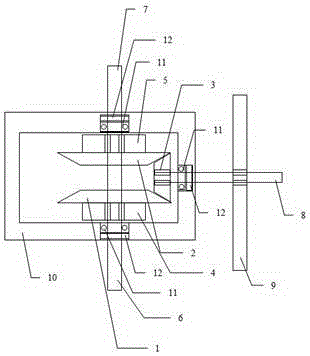
[0016] In the above-mentioned embodiment, an example in which the power input may be unilaterally input or input at the left and right ends with respect to the left half shaft 6 and the right half shaft 7 has been described. However, the present invention does not limit this structure. For example, attach figure 2 As shown, it is also possible to retain only one of the left half shaft 6 or the right half shaft 7 as the input shaft, and the power input end of the other shaft is shortened to hide the inside of the gear box 10.

Deformed example 2

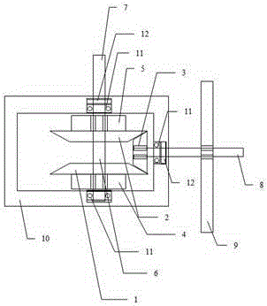
[0018] In the above-mentioned embodiment, an example in which the left half shaft 6 and the right half shaft 7 are integrated, and the power input can be unilaterally input or both left and right ends can be input simultaneously. However, the present invention does not limit this structure. For example, attach image 3 As shown, the intermediate connection between the left half shaft 6 and the right half shaft 7 can be disconnected from each other.

Deformed example 3

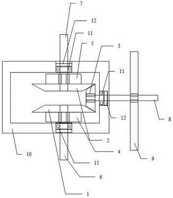
[0020] In the above-mentioned embodiment, an example in which the left half shaft 6 and the right half shaft 7 are integrated, and the power input can be unilaterally input or both left and right ends can be input simultaneously. However, the present invention does not limit this structure. For example, attach Figure 4 As shown, the intermediate connection between the left half shaft 6 and the right half shaft 7 can be disconnected. The first overrunning clutch 4 is installed on the left end of the left half shaft 6 and the second overrunning clutch 5 is installed on the right end of the right half shaft 7. When the swing rotation power is input to the first overrunning clutch 4 and the second overrunning clutch 5 at the same time, the first overrunning clutch 4 captures the forward rotation power and transmits it to the left half shaft 6 and the first gear 1 and the third gear 3 for one-way rotation , The second overrunning clutch 5 captures the reverse rotation power and tr...


PUM


Abstract

The invention relates to a power conversion device with swing rotation changed into unidirectional rotation. According to the device, a driven gear is clamped and engaged between two driving gears on one axis for transmission; two overrun clutches perform forward and backward rotation transmission on reciprocating rotation motion on an input shaft through the two driving gears respectively and drive the driven gear to perform unidirectional rotation output. As the first gear and the second gear are perpendicular to and clamp the left and right of the third gear in an engaged mode, under the action of the first overrun clutch and the second overrun clutch, the first gear and the second gear rotate forward and backward respectively and drive the third gear to rotate unidirectionally, moreover, the three gears rotate in the same direction all the time. The power conversion device is simple in structure, large in load bearing force, stable in power output and particularly applicable to a reversing device of a wave power generation device. Compared with the prior art, the power conversion device has the characteristics of being high in efficiency, low in cost and the like.

Description

Technical field [0001] The invention belongs to the field of mechanical transmission, and particularly relates to a power transmission conversion device that converts two-way power input to one-way power output. Background technique [0002] At present, the swing-rotation-to-unidirectional rotation device occupies an important power conversion functional component in the marine power generation industry, but most of the existing technologies have complex structures and high cost of transmission methods such as hydraulic transmission, one-way work, and spring energy storage. , Poor reliability and low mechanical conversion efficiency. [0003] The invention with a patent application number of 201210213090.3 provides a one-way conversion device. The device consists of two overrunning clutches and five gears to achieve one-way conversion. Although the device can directly convert two-way transmission into one-way transmission, in actual operation Among them, two large gears will alway...

Claims


Application Information

Patent Timeline
Patent Type & Authority Applications(China)
IPC IPC(8): F16H3/14
CPCF16H3/14
Inventor 吴钦发
Owner 吴钦发
Why Eureka
Try Eureka