Drive axle self-locking differential

A differential and drive axle technology, which is applied in the field of drive axle self-locking differentials, can solve the problems of high power consumption, etc., and achieve the effects of prolonging service life, sensitive locking speed, and improving driving ability

Active Publication Date: 2015-12-16
WENLING HUAXIN MACHINERY MFG
View PDF8 Cites 5 Cited by
  • Summary
  • Abstract
  • Description
  • Claims
  • Application Information

AI Technical Summary

Problems solved by technology

[0004] This electromagnetic thrust self-locking differential can prevent the vehicle from slipping on muddy roads, improve vehicle passability, and has a long service life. However, in the locked state, the electromagnetic thrust structure needs continuous power supply, and the power consumption is relatively large.

Method used


Image

  • Drive axle self-locking differential
  • Drive axle self-locking differential
  • Drive axle self-locking differential

Examples


Embodiment 1)

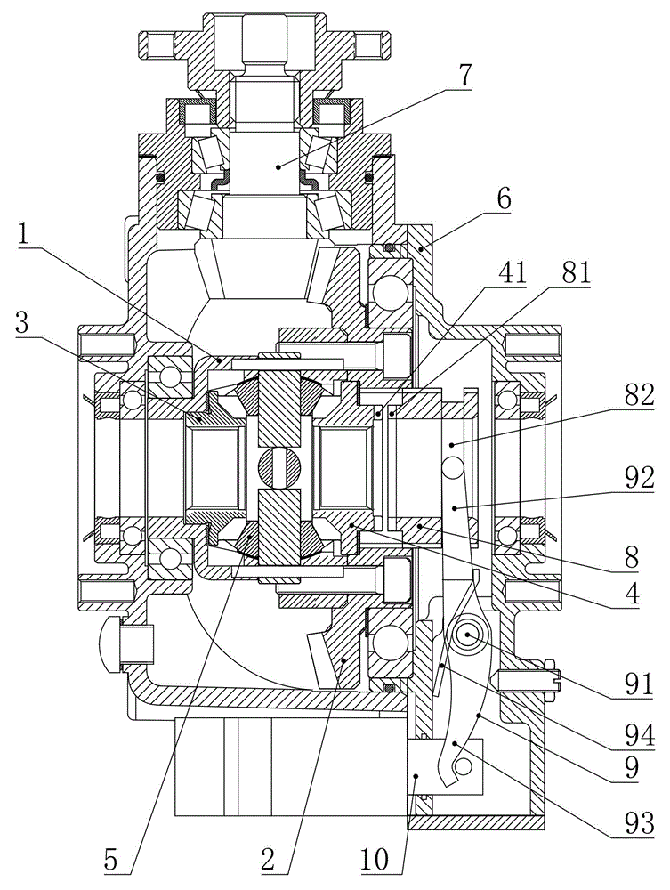
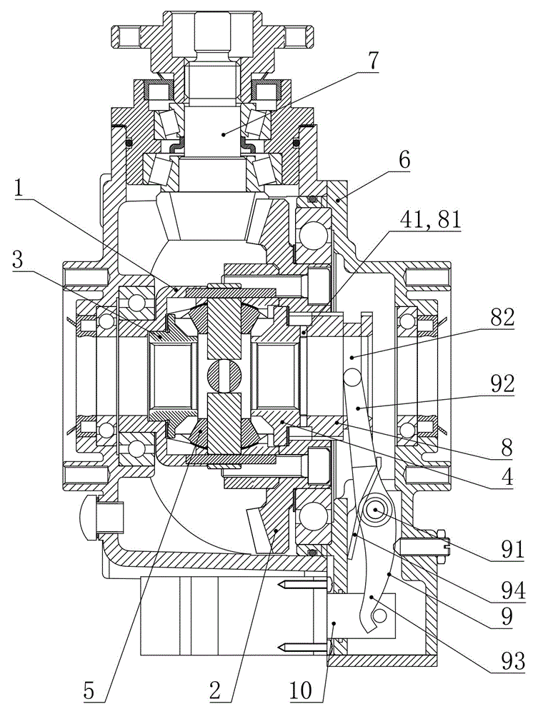
[0028] Such as figure 1 As shown, the transaxle self-locking differential of this embodiment includes a differential case 1 , a transmission gear 2 , a left side gear 3 , a right side gear 4 and a planetary gear 5 . The differential case 1 is rotatably supported in the drive axle case 6, and the transmission gear 2 is a large arc tooth, which is fixedly connected to the differential case 1, and is connected with the input shaft installed in the drive axle case 6. Gear shaft 7 transmission connection. The left side gear 3, the right side gear 4 and the planetary gear 5 are all located in the differential housing 1, wherein the left and right side gears 3, 4 are coaxially arranged with the transmission gear 2, and the planetary gear 5 is respectively connected to the left , Right side shaft gears 3 and 4 mesh simultaneously.

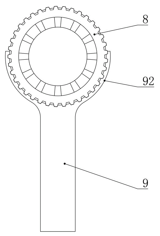
[0029] The right side of the right side gear 4 is coaxially provided with a locking movable sleeve 8, the locking movable sleeve 8 is located in the dif...

Embodiment 2)

[0034] This embodiment is basically the same as Embodiment 1, except that in this embodiment, the right side gear has an extension extending axially to the right, and the circumferential limiting structure includes The first spline and the second spline are located on the inner peripheral surface of the locking movable sleeve, and the first spline and the second spline are arranged in cooperation. When the locking movable sleeve moves to the left, the second spline gradually meshes with the first spline, so that the right side shaft gear is combined with the differential case to realize locking.

Embodiment 3)

[0036] This embodiment is basically the same as Embodiment 1, the difference is that in this embodiment, the right side gear has an extension extending axially to the right and deep into the locking movable sleeve, and the locking movable sleeve passes through the flower The key connection is fixed circumferentially with the extension, and a circumferential limiting structure is provided between the locking movable sleeve and the differential case. The circumferential limiting structure includes end teeth three on the right end surface of the differential housing and end teeth four on the left end surface of the locking movable sleeve, and the end teeth three and end teeth four are arranged in cooperation. When the locking movable sleeve moves to the left, the fourth end tooth gradually meshes with the third end tooth, so that the right side shaft gear is combined with the differential case to realize locking.


PUM


Abstract

The invention discloses a drive axle self-locking differential, belonging to the technical field of mechanical transmission. The drive axle self-locking differential comprises a differential housing and a transmission gear, wherein a left half shaft gear, a right half shaft gear and a planetary gear are arranged in the differential housing, and the transmission gear is connected with an input gear shaft in a transmitting manner; a locking activity set is arranged on the right side of the right half shaft gear, and a thrust structure used for controlling the axial movement of the locking activity set is connected to the locking activity set; the thrust structure comprises a shifting fork and a linear actuator capable of realizing self-locking after power failure, and the shifting fork comprises a shifting fork shaft and a shifting fork body; two shifting fork arms of the shifting fork body are connected to the locking activity set, and the shifting fork is connected to the push rod of the linear actuator; the middle of the shifting fork is hinged to the shifting fork shaft, and a torsional spring is arranged at the hinging position; the shifting fork arms can shift the locking activity set to move left under the action force of the torsional spring, and the linear actuator can overcome the action force of the torsional spring to enable the shifting fork arms to shift the locking activity set to move right. The drive axle self-locking differential has the advantages of being low in power consumption, good in self-locking effect and long in service life.

Description

technical field [0001] The invention relates to the technical field of mechanical transmission, in particular to a differential, especially a drive axle self-locking differential. Background technique [0002] The differential is a device with power transmission and power distribution functions. Its function is to automatically adjust the speed of the inner and outer wheels when the vehicle encounters a turn during driving, so as to ensure that the outer wheels will not be dragged on the road. Avoid increased tire wear, thereby ensuring the safety factor of driving vehicles and improving the operating life of the reducer. Ordinary differentials will slip due to insufficient adhesion when encountering relatively bad road conditions, such as when a certain bridge of an ATV or a farmer's vehicle encounters a muddy and slippery road. [0003] In order to prevent slippage, a Chinese patent disclosed an electromagnetic thrust self-locking differential on June 17, 2015. The author...

Claims


Application Information

Patent Timeline
Patent Type & Authority Applications(China)
IPC IPC(8): F16H48/20F16H48/38
CPCF16H48/20F16H48/38
Inventor 张宇荣
Owner WENLING HUAXIN MACHINERY MFG
Why Eureka
Try Eureka