A system and method for time-domain conversion of internal-combustion engine cylinder pressure signal to angle domain

A technology of in-cylinder pressure and rotation angle, which is applied in the system field of internal combustion engine cylinder pressure signal time domain and rotation angle domain, can solve problems such as encoder installation difficulties, test system error sampling, encoder output signal loss, etc. The device is difficult to fix, the installation requirements are low, and the effect of improving reliability

Active Publication Date: 2017-06-30
SHANDONG UNIV
View PDF5 Cites 2 Cited by
  • Summary
  • Abstract
  • Description
  • Claims
  • Application Information

AI Technical Summary

Problems solved by technology

The encoder shaft and the crankshaft rotate synchronously, requiring high concentricity between the two. If there is a deviation between the centers of the two, it is easy to cause the loss of the encoder output signal, or even the breakage of the encoder shaft, which will adversely affect the reliable operation of the entire test system.
In addition, the output of the encoder is a high-frequency pulse signal, which is sent to the test system for shaping and processing to trigger sampling. There are various interferences such as dynamometers at the engine test site, which may easily lead to false sampling by the test system
[0004] According to the above-mentioned analysis of the existing in-cylinder pressure signal test methods, it can be seen that the existing methods have problems such as inconvenient installation of the sensor, and are easily affected by interference; and because the encoder is difficult to install, the current method can only be applied to laboratory testing occasions , for vehicle engines, due to the limited space at the free end of the engine, it is difficult to test the in-cylinder pressure

Method used


Image

  • A system and method for time-domain conversion of internal-combustion engine cylinder pressure signal to angle domain
  • A system and method for time-domain conversion of internal-combustion engine cylinder pressure signal to angle domain
  • A system and method for time-domain conversion of internal-combustion engine cylinder pressure signal to angle domain

Examples


Embodiment Construction

[0036] The present invention is described in detail below in conjunction with accompanying drawing:

[0037] The present invention proposes a new method for testing the in-cylinder pressure signal in view of the problems of inconvenient installation of the encoder, loss of the encoder signal or being affected by interference and easy sampling abnormality in the current in-cylinder pressure signal testing method. The method has the advantages of convenient sensor installation, reliable operation, etc., can meet the needs of internal combustion engine research and development and production unit cylinder pressure signal test and analysis, and has broad application prospects.

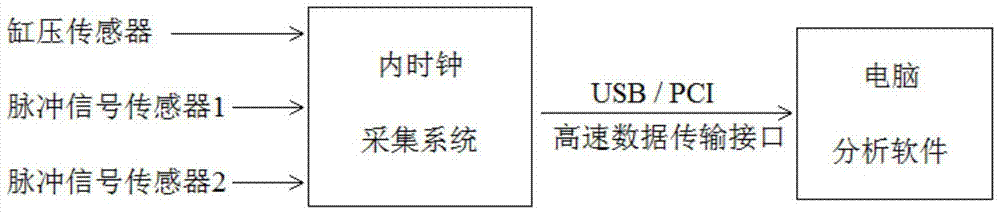
[0038] The invention proposes a test method and system suitable for collecting pressure signals in cylinders, including two parts: a hardware system and a test analysis method.

[0039] 1. Hardware system introduction: The hardware system includes two parts: the sensor and the internal clock data acquisiti...


PUM


Abstract

The invention discloses a system and a method for a time domain and a rotation angle domain of an in-cylinder pressure signal of an internal combustion engine, a cylinder pressure measurement device and a pulse signal measurement device. The cylinder pressure measurement device and the pulse signal measurement device measure the collected in-cylinder pressure signal and the The pulse signal corresponding to the flywheel ring gear is transmitted to the internal clock acquisition system, and the internal clock acquisition system further transmits the received data to the processor for processing; the precise zero-crossing point of the pulse signal is determined by an interpolation algorithm, and on this basis, the in-cylinder The pressure signal is converted from the time domain to the angle domain; this method effectively avoids the problem of false triggering due to the loss or interference of the encoder signal in the traditional test method, and effectively improves the reliability of the data acquisition process.

Description

technical field [0001] The invention relates to a test method for a pressure signal in a cylinder of an internal combustion engine, in particular to a system and a method for converting the pressure signal in a cylinder of an internal combustion engine from a time domain to an angle domain based on an interpolation algorithm. Background technique [0002] The internal combustion engine cylinder pressure signal contains a wealth of information about the combustion process in the cylinder, which can provide important references for the development and performance improvement of internal combustion engines. Every 720-degree crankshaft angle of the internal combustion engine is a working cycle, and the collection and analysis of the pressure signal in the cylinder is based on the crankshaft angle. For this reason, the existing in-cylinder pressure signal testing systems mostly use external clock sampling to test the in-cylinder pressure. This test method requires the use of an ...

Claims


Application Information

Patent Timeline
Patent Type & Authority Patents(China)
IPC IPC(8): G01L23/00
Inventor 纪少波程勇唐娟王洋赵秀亮汪凤娟
Owner SHANDONG UNIV
Why Eureka
Try Eureka