Long-span steel structure pressure arch
A large-span, steel structure technology, applied in the field of large-span column-free structures and large-span steel structure pressure arches, can solve the problems of high cost, limited planting area, small span, etc., and achieve long service life, less material consumption, The effect of high safety
- Summary
- Abstract
- Description
- Claims
- Application Information
AI Technical Summary
Problems solved by technology
Method used
Image
Examples
Embodiment 1
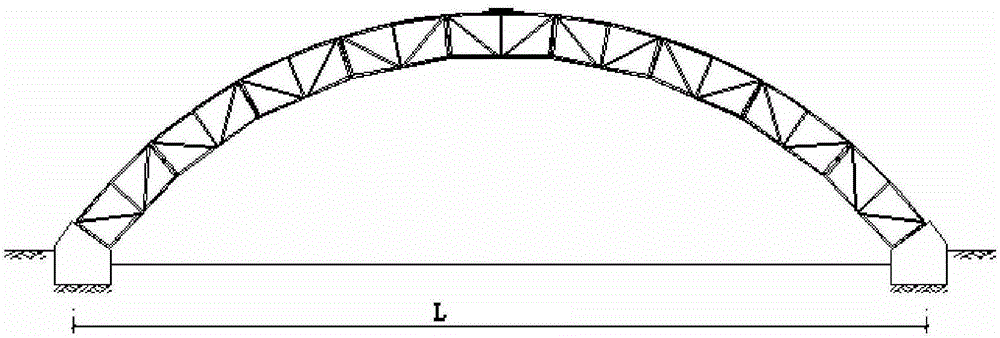
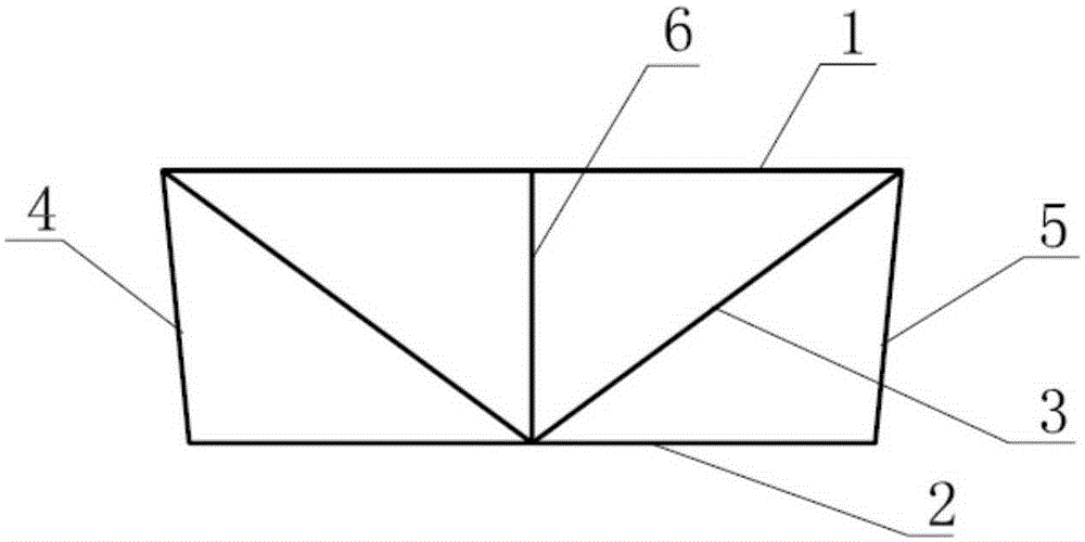
[0025] Such as Figure 1-2 As shown, a long-span steel structure pressure arch is used as a support system for a large-span greenhouse. The pressure arch is composed of a plurality of arched frame units and a supporting base, and a plurality of the arched frame units are connected to form a large-span arch frame, the two ends of the arch frame are connected to the support base, and the number of the arch frame units is preferably an odd number, which can realize a stable symmetrical structure. The support surface of the support base is a slope, providing the arch frame lateral and longitudinal support force, since the arch frame is not provided with columns, the support base mainly provides the longitudinal mechanical support of the arch frame, and the arch frame unit includes: an outer frame rod 1, a first inner frame rod 2 and a A plurality of auxiliary rods 3 and a plurality of reinforcing rods connecting the outer frame rod 1 and the first inner frame rod 2, the plurality ...
Embodiment 2
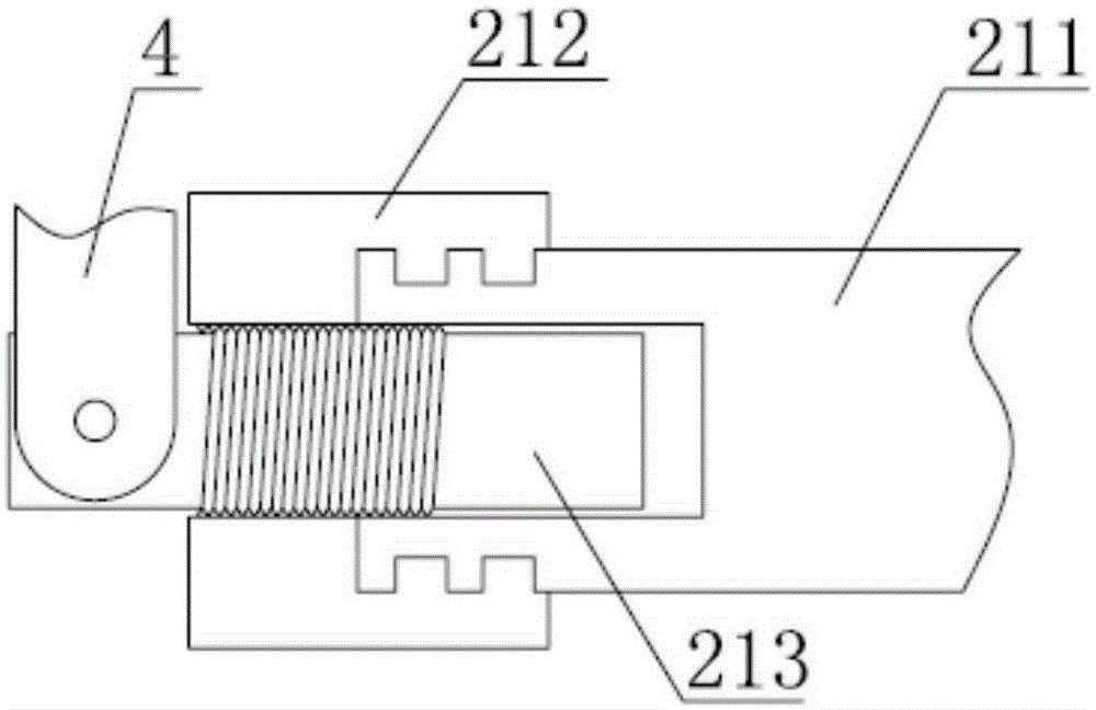
[0031] Such as image 3 As shown, the solution of this embodiment is basically the same as the previous embodiment, the only difference is that the first inner frame rod 2 can be replaced by an adjustable inner frame rod assembly 21, and the adjustable inner frame rod assembly 21 includes: The second inner frame rod 211, the threaded sleeve 212 and the adjusting rod 213, the two ends of the second inner frame rod 211 are provided with circular concave holes, the threaded sleeve 212 is divided into a fixed end and an extension end, and the threaded sleeve The fixed end of 212 is fixed on one end of the second inner frame rod 211, the extension end extends to the outside of the second inner frame rod 211, the fixed end of the threaded sleeve 212 can freely rotate around the axis at one end of the second inner frame rod 211, The inside of the extension end of the threaded sleeve 212 is provided with threads, the adjustment rod 213 is arranged in the concave hole of the second inn...
Embodiment 3
[0033] Such as Figure 4-5 As shown, the scheme of this embodiment is basically the same as the previous embodiment, the only difference is that the reinforcing rod 4 at the first end is provided with a T-shaped groove 41 on one side of the extending direction of the first inner frame rod 2 at the end, so The second end reinforcement bar 5 is provided with a T-shaped protrusion 51 on one side of the extension direction of the inner frame bar 2 at the end, and the T-shaped groove 41 and the T-shaped protrusion 51 are provided with fixing holes. The frame unit can be connected conveniently and quickly through the T-shaped groove 41 and the T-shaped protrusion 51, and by using other connection methods such as pins, screws or welding in the fixing holes, it can play a role in strengthening the fixation.
PUM
 Abstract
Description
Claims
Application Information
 - R&D
- Intellectual Property
- Life Sciences
- Materials
- Tech Scout
- Unparalleled Data Quality
- Higher Quality Content
- 60% Fewer Hallucinations
Browse by: Latest US Patents, China's latest patents, Technical Efficacy Thesaurus, Application Domain, Technology Topic, Popular Technical Reports.
© 2025 PatSnap. All rights reserved.Legal|Privacy policy|Modern Slavery Act Transparency Statement|Sitemap|About US| Contact US: help@patsnap.com


