Fluidized bed reactor

A fluidized bed reactor and reactor technology, applied in chemical instruments and methods, chemical/physical processes, etc., can solve the problems of expansion deformation, poor sealing, aggravated corrosion of the fluid distributor 2, etc. Avoid the effect of a loose seal

Active Publication Date: 2015-12-23
PANZHIHUA IRON & STEEL RES INST OF PANGANG GROUP
View PDF4 Cites 6 Cited by
  • Summary
  • Abstract
  • Description
  • Claims
  • Application Information

AI Technical Summary

Problems solved by technology

The existing fluid distributor 2 is generally arranged in the reactor body 1 and is located at the bottom of the reaction section 4 (that is, close to the reaction center of the fluidized bed reactor), so when the reaction material is corrosive (for example, it is used in the chlorination furnace) Chlorine gas is used as the fluid material), and the fluid distributor 2 is easily corroded. At the same time, because the fluid distributor 2 is close to the reaction center of the fluidized bed reactor, the heat released during the reaction makes the temperature of the reaction center of the fluidized bed reactor rise. Corrosive fluid materials are generally more corrosive at high temperatures, thereby aggravating the corrosion of the fluid distributor 2, thereby reducing the service life of the fluid distributor 2, making it unable to meet the needs of continuous production. The fluid distributor 2 will expand and deform, which will cause a gap between the fluid distributor 2 and the reactor body 1, causing the problem of poor sealing

Method used


Image

  • Fluidized bed reactor
  • Fluidized bed reactor
  • Fluidized bed reactor

Examples


Embodiment Construction

[0029] Specific embodiments of the present invention will be described in detail below in conjunction with the accompanying drawings. It should be understood that the specific embodiments described here are only used to illustrate and explain the present invention, and are not intended to limit the present invention.

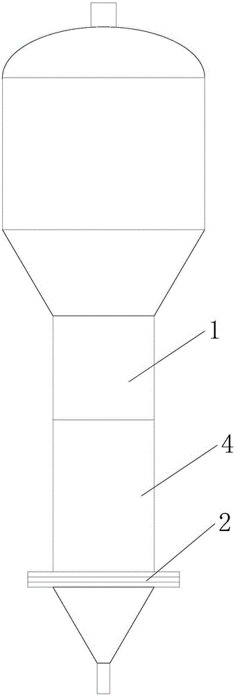
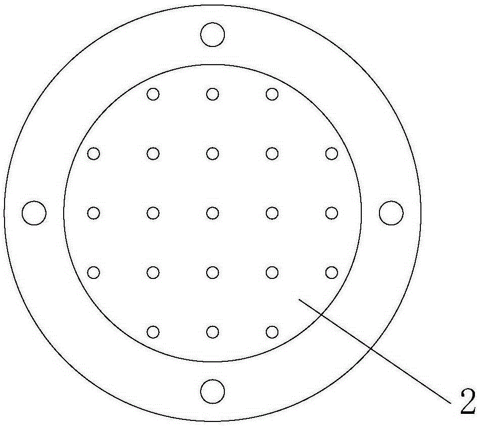
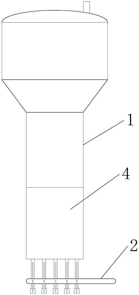
[0030] The invention provides a fluidized bed reactor, specifically, as image 3 and Figure 4 As shown, the fluidized bed reactor includes a reactor body 1 and a fluid distributor 2, the reactor body 1 includes a reaction section 4, a plurality of fluid distribution holes 3 are formed at the bottom of the reaction section 4, and the fluid The distributor 2 includes a conveying pipe connected to each of the fluid distribution holes 3, so as to convey the fluid material into the reaction section 4 through the conveying pipe.

[0031] It should be noted that the specific type of the fluidized bed reactor and the specific structural form of the reactor body 1 and...


PUM


Abstract

The present invention relates to the field of fluidized bed reactors, and discloses a fluidized bed reactor. The fluidized bed reactor comprises: a reactor main body (1) and a fluid distributor (2), wherein the reactor main body (1) comprises a reaction zone (4), wherein a plurality of fluid distribute holes (3) are formed in the bottom of the reaction zone (4), and the fluid distributor (2) comprises conveyor pipes that are connected with the fluid distribute holes (3), so that fluid materials can be conveyed to the reaction zone (4) by the conveyor pipes. The fluidized bed reactor disclosed by the present invention has the advantage that the fluid distributor is difficult to be corroded.

Description

technical field [0001] The invention relates to the field of fluidized bed reactors, in particular to a fluidized bed reactor. Background technique [0002] The fluidized bed reactor is a reactor that uses gas or liquid to pass through the granular solid layer to keep the solid particles in a state of suspension and movement, and to perform a gas-solid phase reaction process or a liquid-solid phase reaction process. At present, fluidized bed reactors have been widely used in chemical industry, petroleum, metallurgy, nuclear industry and other departments. [0003] like figure 1 As shown, the existing fluidized bed reactor generally includes a reactor body 1 with a reaction section 4 and a fluid distributor 2 (also known as a fluid distribution plate) arranged in the reactor body 1 and at the bottom of the reaction section 4, The fluid distributor 2 generally adopts a perforated plate design (such as figure 2 shown), the main function of the fluid distributor 2 is to make...

Claims


Application Information

Patent Timeline
Patent Type & Authority Applications(China)
IPC IPC(8): B01J8/24
Inventor 尹国亮刘森林龙盘忠杜明李冬勤
Owner PANZHIHUA IRON & STEEL RES INST OF PANGANG GROUP
Why Eureka
Try Eureka