Detachable multifunctional feeding device of dry-method grinding equipment and disassembling and assembling method of detachable multifunctional feeding device

A feeding device and multi-functional technology, which is applied in the field of detachable multi-functional feeding devices, can solve the problems of unreasonable inclination angle of the feeding liner, reducing the operation rate of the equipment, and reducing the production capacity of the mill, so as to reduce the maintenance and replacement time. And manpower and material resources, reduce cost input, increase the effect of output

Active Publication Date: 2015-12-23
CITIC HEAVY INDUSTRIES CO LTD
View PDF10 Cites 1 Cited by
  • Summary
  • Abstract
  • Description
  • Claims
  • Application Information

AI Technical Summary

Problems solved by technology

[0004] Due to the unreasonable inclination angle of the feed liner, there will be material stoppage and material staining. The blocked material will directly enter the feed chute through the gap of the feed liner. When the accumulated material cannot be discharged in time and becomes return material, It will block the feed inlet, resulting in a decrease in mill productivity; too much material may also overflow through the air inlet and cause environmental pollution
[0005] In addition, when there is a problem in the warehouse of the existing dry grinding equipment, it is necessary to remove the grinding door and the grinding door of the grinding equipment when the chamber of the existing dry grinding equipment is shut down for maintenance or when the grinding body wears to a certain extent and needs to be added. Lining plates, pressure beams, gaskets, gap fillers and various accessories are not only troublesome to disassemble, but also the grinding body is lifted up and thrown out through the liners with certain structural characteristics during the movement of the mill, smashing the materials, and grinding After the machine has been running for a period of time, the material is broken through the interaction between the grinding body and the material, and the grinding body is lost to tiny particles, some of which can enter the gap between the grinding door liner and the cylinder liner, and are firmly stuck The grinding door and the lining board of the grinding door make it difficult to disassemble the grinding door. According to the on-site investigation, not only special tools are required to disassemble the grinding door, but also difficult to disassemble, time-consuming and laborious. If necessary, all the lining boards around the manhole must be removed. Go, greatly reducing the operating rate of the equipment
In addition, the grinding body is generally added through the grinding door. The grinding door is far away from the starting position of the first warehouse. During the operation of the mill, the grinding body is gradually brought up and thrown to the side far from the starting position to smash the material. Therefore, a There are fewer grinding bodies and more materials at the initial position of the warehouse, and the grinding efficiency is poor, which leads to the shortening of the effective grinding length of the first chamber of the mill, which seriously affects the output

Method used


Image

  • Detachable multifunctional feeding device of dry-method grinding equipment and disassembling and assembling method of detachable multifunctional feeding device
  • Detachable multifunctional feeding device of dry-method grinding equipment and disassembling and assembling method of detachable multifunctional feeding device
  • Detachable multifunctional feeding device of dry-method grinding equipment and disassembling and assembling method of detachable multifunctional feeding device

Examples


Embodiment Construction

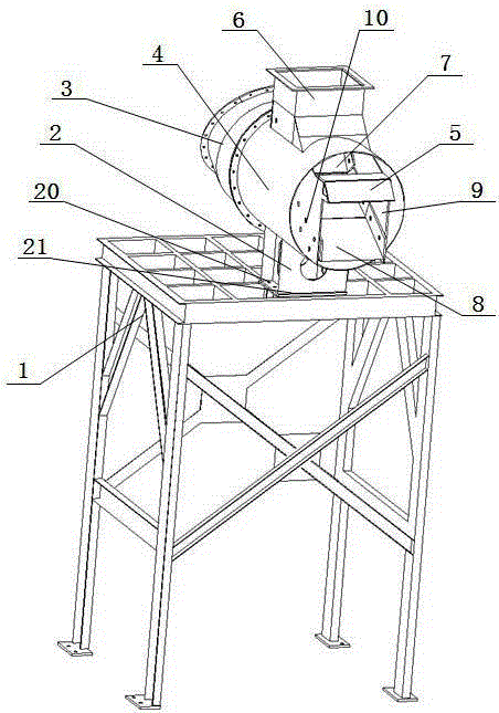
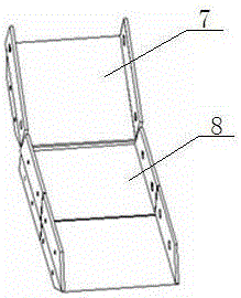
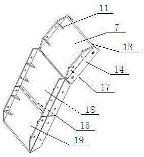
[0037] As shown in the figure, the detachable multifunctional feeding device of the dry grinding equipment is provided with a horizontal feeding chute 4, one end of the feeding chute 4 is connected to a return pipe 3, and the other end extends into the In the grinding bin 12 of the dry grinding equipment, the upper part of the feed chute 4 is provided with a feed inlet 6, and the inside of the feed chute 4 is provided with a combined hopper I7 and a combined hopper that are connected together and have different slopes. Ⅱ8 is used to accept the material falling from the feed port 6 and transport it to the mill bin 12. There is a docking gap between the combined hopper Ⅰ7 and the combined hopper Ⅱ8 to meet the ventilation requirements. The butt gap is 15~ 25mm, it can be designed as 20mm to prevent material leakage. The gap should not be too large or too small. If the gap is too large, the material will enter the feeding chute along this gap to form return material.

[0038] Bot...


PUM


Abstract

The invention relates to a feeding device of dry-method grinding equipment and a disassembling and assembling method of the feeding device, in particular to a detachable multifunctional feeding device of the dry-method grinding equipment and a disassembling and assembling method of the detachable multifunctional feeding device. A horizontal feeding articulated chute is provided, two combined type hoppers with different gradients are arranged in the feeding articulated chute and are in butt joint with each other, and each combined type hopper is composed of a U-shaped wear-resisting component and wear-resisting side plates. Each U-shaped wear-resisting component is composed of a bottom plate, lateral plates arranged on the two sides of the back of the bottom plate and reinforcing rib plates arranged between the bottom plate and the lateral plates. The corresponding wear-resisting side plates are arranged on the two sides of the front face of each bottom plate. The two combined type hoppers are detachably connected with two fixing plates arranged in the feeding articulated chute through the respective wear-resisting side plates, the respective lateral plates and multiple bolts with tenons. By dismantling the bolts with the tenons for connecting the U-shaped wear-resisting components of the combined type hoppers and the fixing plates, parts, prone to being abraded, of the feeding device can be disassembled and replaced. According to the detachable multifunctional feeding device and the disassembling and assembling method thereof, the parts, prone to being abraded, of the feeding device can be conveniently disassembled and replaced, and the feeding device can become a channel for repairing staff to enter a grinding bin.

Description

technical field [0001] The invention relates to a feeding device of dry grinding equipment and a disassembling method thereof, in particular to a detachable multifunctional feeding device of dry grinding equipment and a disassembling method thereof. Background technique [0002] Dry ball mill is a typical equipment for re-crushing after crushing materials. It is mainly used in chemical industry, mineral processing, building materials, metallurgy and other industries. The cement mill feeding device is an important part for conveying materials into the tube mill for grinding. It is composed of a feed inlet, a feed chute, a feed liner and other accessories. The feed liner is welded and assembled at a certain inclination angle. On the feed chute, it plays the role of protecting the feed chute and delaying its wear. The life of the feed liner is directly related to the operation rate and maintenance cost of the equipment. [0003] When working, the material falls on the feeding ...

Claims


Application Information

Patent Timeline
Patent Type & Authority Applications(China)
IPC IPC(8): B02C23/02
Inventor 闫玲娣曹桂月陈松战杜强和蕴锋赵淑洁倪小令赵卫峰袁龙李超王金虎张益阔陈明凯古创国
Owner CITIC HEAVY INDUSTRIES CO LTD
Why Eureka
Try Eureka