
Vertical reaction furnace for continuous production of carbon nanotubes with preset catalyst

A carbon nanotube and catalyst technology, which is applied in the field of chemical vapor deposition process equipment manufacturing, can solve the problems of difficult working conditions, reduce production efficiency, waste useless time, etc., and achieve the effects of improving working conditions, improving production efficiency, and reducing productivity.

Active Publication Date: 2015-12-23
江西晶纳新材料有限公司
View PDF4 Cites 5 Cited by
  • Summary
  • Abstract
  • Description
  • Claims
  • Application Information

AI Technical Summary

Problems solved by technology

[0005] The main disadvantages of producing carbon nanotubes in a horizontal intermittent chemical vapor deposition furnace are: 1. When workers operate continuously, they need to open the furnace door to take out the product and place a new catalyst at the same time, so the working conditions are difficult; 2. The production efficiency is low
It takes useless time to open the furnace door, take out the product, and place a new catalyst. After closing the furnace door, the furnace gas must be exhausted again, which consumes the effective growth time of carbon nanotubes and reduces production efficiency.
3. The power cannot be turned off during the interval between the production of carbon nanotubes, so the energy consumption of the production of carbon nanotubes is increased

Method used


Image

  • Vertical reaction furnace for continuous production of carbon nanotubes with preset catalyst

Examples


Embodiment Construction

[0031] The present invention will be further described below in conjunction with accompanying drawing.

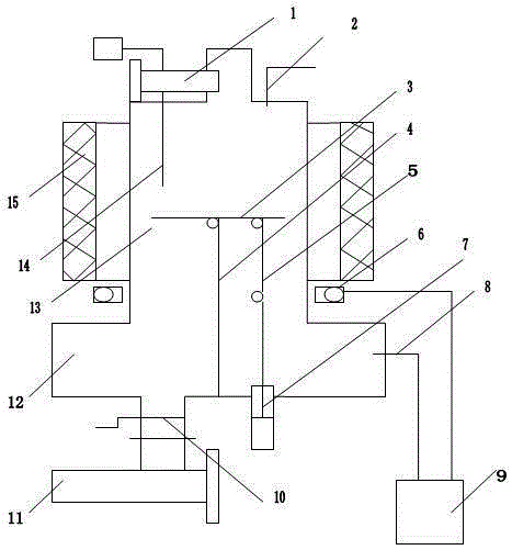
[0032]1. The working process is as follows: the heating furnace 15 starts, the temperature of the reaction chamber 12 rises, the inert gas enters from the inlet nozzle 2, and the air in the reaction chamber 13 is evacuated. When the temperature in the reaction chamber 13 reaches 400 degrees, the catalyst feeder 1 is delivered Work, quantitatively feed the catalyst, under the action of gravity, the catalyst settles on the carbon nanotube growth plate 3, at this time, send in hydrogen as the reducing gas through the inlet nozzle 2, and the reducing catalyst changes from an oxidized metal to a nano-sized metal with catalytic activity particles. Continue heating, when the reaction chamber 13 temperature reaches the carbon nanotube formation temperature, enter the carbon source gas from the inlet nozzle 2, close the hydrogen or inert gas, at this time the carbon source gas crack...


PUM


Abstract

The invention relates to a vertical reaction furnace for continuous production of carbon nanotubes with a preset catalyst. The reaction furnace comprises a heating furnace, a reaction chamber, a collecting chamber, a carbon nanotube growth plate, a growth plate support column, a growth plate push rod, and a pneumatic push rod valve, etc. The reaction chamber is located in the heating furnace, and the carbon nanotube growth plate is located at the center of the reaction chamber. The carbon nanotube growth plate and the growth plate support column are in hinged connection, and the growth plate support column is vertically fixed at the center of the collecting chamber base plate. One end of the growth plate motion push rod is in hinged connection with the carbon nanotube growth plate, and the other end is in hinged connection with the pneumatic push rod valve. The reaction furnace provided by the invention can realize continuous production of carbon nanotubes, and can effectively and fully exert the catalytic efficiency of the catalyst in a carbon nanotube deposition process. The tail gas of carbon nanotube deposition is utilized, the energy consumption for production of unit weight carbon nanotube can be reduced, the carbon nanotube production cost is lowered, and the equipment structure is simpler.

Description

technical field [0001] The invention belongs to the field of chemical vapor deposition process equipment manufacturing, and relates to nanometer material manufacturing equipment. Background technique [0002] Carbon nanotubes are a new one-dimensional nanocrystalline material with many excellent properties. Some new fields have been developed in commercial applications, and they have begun to replace carbon black and graphite in many traditional application fields, and have become additive products designated by downstream manufacturers. . [0003] Catalyst chemical vapor deposition process is the main method for industrial mass production of carbon nanotubes. The main process features of the pre-catalyst chemical vapor deposition process associated with the present invention are: 1. Carbon source gas is used as the carbon source for the growth of carbon nanotubes. 2. The reaction chamber is at high temperature and lacks oxygen, providing a carbon source gas cracking envir...

Claims


Application Information

Patent Timeline
Patent Type & Authority Applications(China)
IPC IPC(8): C01B31/02B82Y30/00
Inventor 曾效舒曾志鹏
Owner 江西晶纳新材料有限公司
Learn More