
Let the pressure anchor assembly

A bolt and assembly technology, which is applied in the installation of bolts, sheet pile walls, mining equipment, etc., can solve the problems that cannot meet the needs of large deformation of surrounding rock, high material ductility requirements, engineering instability and damage, and achieve resistance Constant, large controllable range, and the effect of meeting the needs of large deformation

Active Publication Date: 2017-04-05
CHONGQING JIAOTONG UNIVERSITY
View PDF5 Cites 0 Cited by
  • Summary
  • Abstract
  • Description
  • Claims
  • Application Information

AI Technical Summary

Problems solved by technology

[0002] Bolt is the most commonly used anchoring structure in geotechnical engineering. It has a large number of applications in slope support engineering, tunnel surrounding rock support, mining roadway support and other fields; traditional bolt is basically a rigid structure, which is resistant to deformation The tolerance is small; when the quality of the rock mass is poor and the deformation is large, and when dynamic loads such as earthquakes and blasting vibrations act, the bolts are pulled off and cause engineering instability and damage. In the case of large deformation of surrounding rock, it is a better engineering solution to use anchors that can allow large deformations; at present, there are new types of anchors that provide large deformations through the ductility of the anchor body itself. This type of anchor structure is the same as Ordinary bolts are not much different, but they have high requirements on the ductility of the material, and the allowable deformation is generally still small, the bearing capacity is low, and the resistance is not constant, which cannot meet the needs of large deformation of the surrounding rock.

Method used


Image

  • Let the pressure anchor assembly
  • Let the pressure anchor assembly
  • Let the pressure anchor assembly

Examples


Embodiment Construction

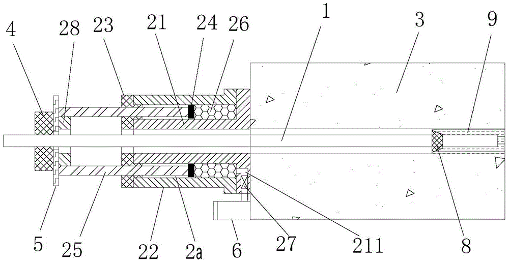
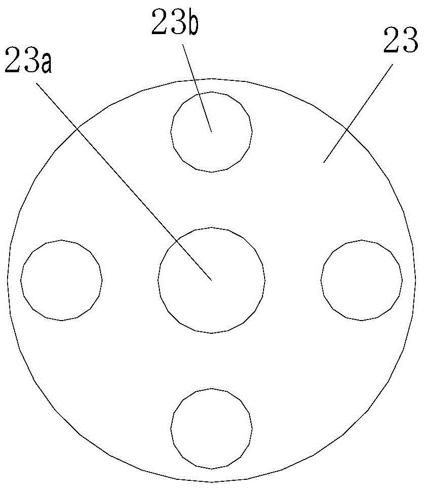
[0020] figure 1 It is a structural schematic diagram of the present invention, figure 2 It is a top view of the cylinder head of the present invention, as shown in the figure: the yielding anchor rod assembly of the present embodiment includes the anchor rod body 1 and the pressure relief mechanism provided on the anchor rod body 1 for pressure relief. The pressure letting mechanism is a compression cylinder structure and includes an inner cylinder body 21, an outer cylinder body 22, a cylinder head 23, a piston ring 24 and a piston rod 25; the inner cylinder body 21 is a hollow cylinder, and the cylinder head 23 is provided with The central hole 23a and the rod hole 23b matched with the piston rod 25, the anchor rod body 1 passes through the hollow part of the inner cylinder body 21 and the central hole 23a of the cylinder head 23 and is linked with the piston rod 25; the inner cylinder body 21. The outer cylinder body 22 and the cylinder head 23 form a working chamber 2a w...


PUM


Abstract

The invention discloses a yielding type anchor rod assembly which comprises an anchor rod body and a yielding mechanism. The yielding mechanism is of a compression cylinder structure and comprises an inner cylinder body, an outer cylinder body, a cylinder cover, a piston ring and piston rods. The inner cylinder body is a hollow cylindrical body, the cylinder cover is provided with a central hole and rod holes matched with the piston rods, and the anchor rod body penetrates through the hollow portion of the inner cylinder body and the central hole of the cylinder cover and is linked with the piston rods. The inner cylinder body, the outer cylinder body and the cylinder cover form a working cavity with an annular cross section. The piston ring is arranged in the working cavity, the top of the piston ring is connected with at least two piston rods, and compression media are arranged between the bottom of the piston ring and the bottom of the working cavity. The piston rods penetrate out from the rod holes and can be driven by the anchor rod body to move. A pressure relief channel is formed in the bottom of the inner cylinder body, and a safety valve capable of being opened and closed automatically according to a preset pressure value is mounted in the pressure relief channel. According to the yielding type anchor rod assembly, the allowed deformation is large, the bearing capacity is high, the resistance is constant, and the requirement for large deformation of surrounding rocks can be met.

Description

technical field [0001] The invention relates to a geotechnical engineering anchoring device, in particular to a pressure-yielding anchor rod assembly. Background technique [0002] Bolt is the most commonly used anchoring structure in geotechnical engineering. It has a large number of applications in slope support engineering, tunnel surrounding rock support, mining roadway support and other fields; traditional bolt is basically a rigid structure, which is resistant to deformation The tolerance is small; when the quality of the rock mass is poor and the deformation is large, and when dynamic loads such as earthquakes and blasting vibrations act, the bolts are pulled off and cause engineering instability and damage. In the case of large deformation of surrounding rock, it is a better engineering solution to use anchors that can allow large deformations; at present, there are new types of anchors that provide large deformations through the ductility of the anchor body itself. ...

Claims


Application Information

Patent Timeline
Patent Type & Authority Patents(China)
IPC IPC(8): E02D5/74E02D33/00E21D21/00
Inventor 蒋海飞赵宁雨董天雄谢远光厉彥君张扬帆凌学鹏
Owner CHONGQING JIAOTONG UNIVERSITY
Learn More