
Noise reduction and purification device for automobile exhaust gas

A technology for purification devices and automobile exhaust, which is applied in the direction of mufflers, exhaust devices, engine components, etc., and can solve problems such as cavitation purification liquid, troublesome replacement process, and retention

Active Publication Date: 2015-12-23
方冰熔
View PDF5 Cites 5 Cited by
  • Summary
  • Abstract
  • Description
  • Claims
  • Application Information

AI Technical Summary

Problems solved by technology

[0002] The existing automobile exhaust noise reduction and purification device adopts the structure of lengthening the tailpipe and simply adding several layers of filter screens on the tailpipe. This structure has a poor purification effect, and the filter screen needs to be replaced frequently, and the replacement process is also relatively troublesome. There is also a method of directly bubbling the exhaust gas through the purification liquid, that is, injecting the exhaust gas into the purification liquid completely, and then bubbling out from the surface of the purification liquid. In this way, only the part of the exhaust gas on the surface of the bubbles is in contact with the purification liquid, and the middle part is difficult to Purification, the purification effect is poor, and when the exhaust gas volume is small or the discharge force is not enough, it is easy to cause cavitation or purification liquid retention, and even in cold weather, the purification liquid freezes and causes no ventilation

Method used


Image

  • Noise reduction and purification device for automobile exhaust gas
  • Noise reduction and purification device for automobile exhaust gas

Examples


Embodiment Construction

[0018] Specific embodiments of the present invention will be described in detail below in conjunction with the accompanying drawings.

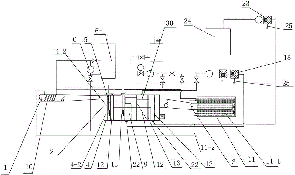
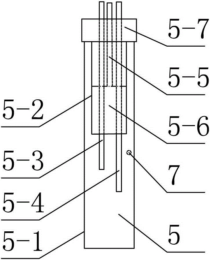
[0019] Such as figure 1 , figure 2 As shown, a kind of automobile exhaust noise reduction and purification device provided by the present invention includes an exhaust gas inlet 1, a noise reduction and purification device main body 2, and a discharge outlet 3. After purification, it is discharged from the discharge outlet. The main body 2 of the noise reduction and purification device includes a primary purification chamber 4, and the primary purification chamber 4 is provided with a purification pool 4-1 and an air-water purification chamber 4-2. The purification pool 4- 1 is provided with a purification liquid, the tail gas inlet 1 is connected to the first-level purification chamber 4, and the upper edge of the opening of the tail gas inlet 1 is higher than the upper surface of the purification liquid in the purification pool 4-1, and th...


PUM


Abstract

The invention provides a noise reduction and purification device for automobile exhaust gas. The noise reduction and purification device is simple in structure and good in purification effect and comprises an exhaust gas inlet, a noise reduction and purification device body and an exhaust outlet. Exhaust gas enters the noise reduction and purification device body through the exhaust gas inlet and then exhausted through the exhaust outlet after noise reduction and purification are performed on the exhaust gas through the noise reduction and purification device body. The noise reduction and purification device body comprises a first-grade purification chamber. A purification pool and a gas-water purification cavity are arranged inside the first-grade purification chamber. A purification solution is contained inside the purification pool. The exhaust gas inlet is communicated with the first-grade purification chamber. The upper edge of an opening of the exhaust gas inlet is higher than the upper surface of the purification solution inside the purification pool. A water level indicator is arranged inside the purification pool of the first-grade purification chamber and induces the height of the purification solution inside the purification pool. The purification pool is connected with a purification solution adding pump. The purification solution adding pump supplements the purification solution inside the purification pool. An atomization filter net is arranged between the gas-water purification cavity and the purification pool. A gas-water separation filter net is arranged at an outlet of the gas-water purification cavity.

Description

technical field [0001] The invention relates to an automobile tail gas muffler and purification device. Background technique [0002] The existing automobile exhaust noise reduction and purification device adopts the structure of lengthening the tailpipe and simply adding several layers of filter screens on the tailpipe. This structure has a poor purification effect, and the filter screen needs to be replaced frequently, and the replacement process is also relatively troublesome. There is also a method of directly bubbling the exhaust gas through the purification liquid, that is, injecting the exhaust gas into the purification liquid completely, and then bubbling out from the surface of the purification liquid. In this way, only the part of the exhaust gas on the surface of the bubbles is in contact with the purification liquid, and the middle part is difficult to Purification, its purification effect is poor, and when the exhaust gas volume is small or the discharge force i...

Claims


Application Information

Patent Timeline
IPC IPC(8): F01N3/022F01N3/04F01N3/08F01N13/00
CPCF01N3/022F01N3/04
Inventor 方冰熔
Owner 方冰熔
Learn More