Energy-saving balance high-pressure valve and design method

A high-pressure valve and balancing technology, applied in the field of pressure valve equipment, can solve the problems of complex structure in the valve, low sealing level, affecting the flow of the medium, etc., and achieve the effect of improving the passing rate of the medium, avoiding the blocking of the medium, and simplifying the processing technology.

Inactive Publication Date: 2015-12-23
四川华林自控科技有限公司
View PDF5 Cites 12 Cited by
  • Summary
  • Abstract
  • Description
  • Claims
  • Application Information

AI Technical Summary

Problems solved by technology

[0002] At present, the high-pressure valves in the prior art are mostly single-seat valves and double-seat valves. Regardless of whether the pressure difference is large or small, the valve core and stem of the single-seat structure will receive a lot of upward force as the valve pressure increases. If the pressure is large, the output force of the actuator is required to be greater, and vice versa, when the pressure and pressure difference are too large, the output force of the actuator is required to be too large, which will easily cause the valve core to oscillate.
And its "S" type flow path is complicated, which affects the medium circulation; although the double-seat valve can be applied to the high pressure difference, its internal structure is complex, its processing and assembly precision are high, and the medium flow path is complicated, because the double-seat seal Therefore, compared with the single-seat structure, its sealing level is not high, and it is easy to leak

Method used


Image

  • Energy-saving balance high-pressure valve and design method
  • Energy-saving balance high-pressure valve and design method

Examples


Embodiment Construction

[0030] The technical solutions of the present invention will be clearly and completely described below in conjunction with the accompanying drawings of the present invention. Apparently, the described embodiments are only some of the embodiments of the present invention, not all of them. Based on the embodiments of the present invention, all other embodiments obtained by persons of ordinary skill in the art without creative efforts fall within the protection scope of the present invention.

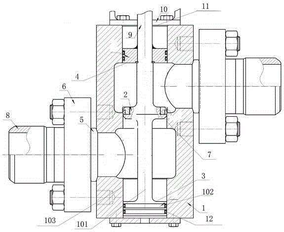
[0031] Such as figure 1 The energy-saving balanced high-pressure valve shown includes a valve body 1, a valve core 2, an inflow side piston device 3, an outflow side piston device 4, a lens pad 5, a threaded pressure plate 6, a valve seat 7, a connecting pipe 8, and a valve stem 9 and the bonnet 10, the end of the valve stem 9 is located inside the valve body 1 through the bonnet 10, the valve core 2 and the valve seat 7 are both located inside the valve body 1, and the valve core 2 is con...


PUM


Abstract

The invention provides an energy-saving balance high-pressure valve. The energy-saving balance high-pressure valve comprises a valve body, a valve element, an inflow side piston device, an outflow side piston device, a lens gasket, a thread pressure plate, a valve seat, connection pipes, a valve rod and a valve deck. The tail end of the valve rod penetrates through the valve deck and is located inside the valve body. The valve element and the valve seat are located inside the valve body. The valve seat is installed on the inner surface of the valve body. The valve body is in a sleeve shape and connected with the valve deck. The inflow side piston device and the outflow side piston device are arranged at the two ends of the valve element respectively. The inflow side piston device and the outflow side piston device each comprise a piston rod, a piston and a piston cylinder. The two connection pipes are connected with the valve body through the lens gasket and the thread pressure plate. A design method comprises the three steps of determining the operation work environment of the valve, checking the pressure difference before and after the valve and carrying out production and manufacturing. On the one hand, medium acting force applied on the valve element can be effectively counteracted; on the other hand, the vibration phenomenon of the valve element in the use process is effectively avoided, the medium blockage phenomenon is avoided, and the production cost can be reduced at the same time.

Description

technical field [0001] The invention relates to a pressure valve device, in particular to an energy-saving balanced high-pressure valve. Background technique [0002] At present, the high-pressure valves in the prior art are mostly single-seat valves and double-seat valves. Regardless of whether the pressure difference is large or small, the valve core and stem of the single-seat structure will receive a lot of upward force as the valve pressure increases. The larger the output force of the actuator is, the greater the output force of the required actuator is, and vice versa, when the pressure and pressure difference are too large, the output force of the actuator is required to be too large, which will easily cause the valve core to oscillate. And its "S" type flow path is complicated, which affects the medium circulation; although the double-seat valve can be applied to the high pressure difference, its internal structure is complex, its processing and assembly precision a...

Claims


Application Information

Patent Timeline
Patent Type & Authority Applications(China)
IPC IPC(8): F16K1/00F16K1/36F16K1/32F16K27/02
CPCF16K1/00F16K1/32F16K1/36F16K27/02
Inventor 夏尚森
Owner 四川华林自控科技有限公司
Why Eureka
Try Eureka