Double-layer parallel flow condenser for integrated passenger car air conditioner

An integrated condenser technology, applied in the direction of evaporator/condenser, refrigerator, refrigeration components, etc., can solve the problems that the air intake area cannot be greatly changed, and the length direction of the front windward condenser cannot be lengthened, etc., to achieve Filling the gap in the market, the effect of small structure size and good pressure resistance

Inactive Publication Date: 2015-12-23
ZHENGZHOU KELIN VEHICLE AIR CONDITIONING
View PDF6 Cites 2 Cited by
  • Summary
  • Abstract
  • Description
  • Claims
  • Application Information

AI Technical Summary

Problems solved by technology

[0002] At present, due to its integrated structure, short length, light weight, and convenient installation, the front windward air conditioner is widely used and popularized at present. Due to the increasing size of the current models and the emergence of ultra-high temperature weather, the air conditioner load requirements are getting higher and higher. However, since the air inlet is in the direction of the front of the car, the air inlet area cannot change greatly, and the length direction of the front windward condenser cannot increase with the cooling capacity; and the refrigerant in the traditional parallel flow condenser does not stratify, Its temperature is the same temperature, which will cause the parallel flow condenser to increase in height and thickness along the air flow direction, and the heat transfer will no longer increase

Method used


Image

  • Double-layer parallel flow condenser for integrated passenger car air conditioner
  • Double-layer parallel flow condenser for integrated passenger car air conditioner
  • Double-layer parallel flow condenser for integrated passenger car air conditioner

Examples


Embodiment Construction

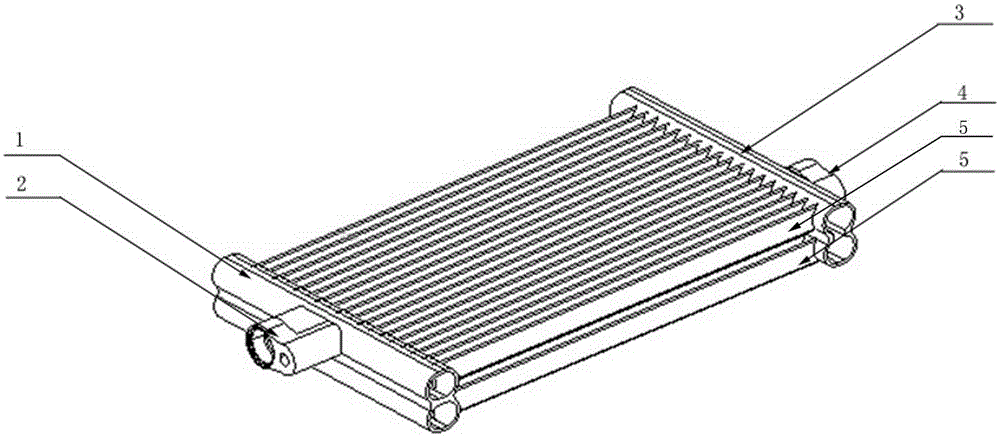
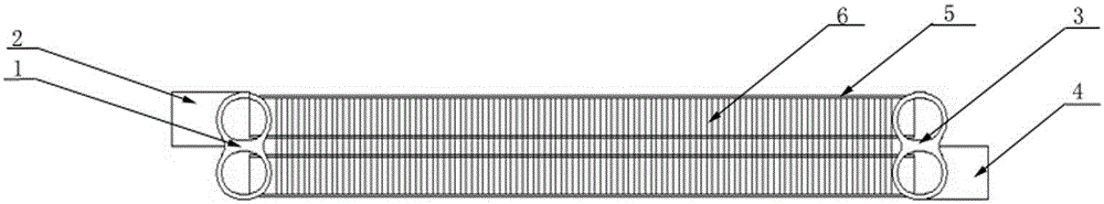
[0016] A double-layer parallel-flow condenser for an integrated passenger car air conditioner, such as figure 1 As shown, it includes a double-layer heat transfer system. The double-layer heat transfer system consists of a double-layer parallel flow refrigerant left header 1, a refrigerant inlet 2 installed on the upper tube of the double-layer parallel flow refrigerant left header 1, and a double-layer parallel flow refrigerant left header 1. Laminar parallel flow refrigerant right header 3, refrigerant outlet 4 installed on the lower tube of double layer parallel flow refrigerant right header 3, connecting double layer parallel flow refrigerant left header 1 and double layer parallel flow refrigerant right The header 3 consists of two layers of horizontally arranged heat transfer flat tubes 5 and heat transfer fins 6 arranged on the heat transfer flat tubes 5. The double-layer parallel flow refrigerant passes through the upper tube and the lower tube of the left header 1. Th...


PUM


Abstract

The invention provides a double-layer parallel flow condenser for an integrated passenger car air conditioner. The double-layer parallel flow condenser comprises a double-layer heat transfer system. The double-layer heat transfer system is composed of a left double-hole header, a right double-hole header, a refrigerant inlet formed in an upper pipe of one double-hole header, a refrigerant outlet formed in a lower pipe of the other double-hole header, two layers of horizontal heat transfer flat pipes connected with the two double-hole headers, and heat transfer fins arranged on the heat transfer flat pipes. The upper pipes and the lower pipes of the double-hole headers are communicated through conduction holes. The layering heat transfer technology is adopted, effective utilization of the temperature gradient is achieved, and the heat transfer temperature difference is effectively improved. The heat exchange amount of the parallel flow condenser is greatly increased, the breakthrough of the heat exchange amount is achieved, and compared with a current traditional double-D type header condenser, better pressure resistance is achieved. According to integrated welding molding, the machining cost is reduced, and the market vacancy is filled up. The double-layer parallel flow condenser has the beneficial effects of being small in structural size, high in efficiency, low in cost, wide in application range and the like.

Description

technical field [0001] The invention belongs to the heat transfer field of passenger car air conditioners, and in particular relates to an integrated double-layer parallel flow condenser for passenger car air conditioners. Background technique [0002] At present, due to its integrated structure, short length, light weight, and convenient installation, the front windward air conditioner is widely used and popularized at present. Due to the increasing size of the current models and the emergence of ultra-high temperature weather, the air conditioner load requirements are getting higher and higher. However, since the air inlet is in the direction of the front of the car, the air inlet area cannot change greatly, and the length direction of the front windward condenser cannot increase with the cooling capacity; and the refrigerant in the traditional parallel flow condenser does not stratify, Its temperature is the same temperature, which will cause the parallel flow condenser t...

Claims


Application Information

Patent Timeline
Patent Type & Authority Applications(China)
IPC IPC(8): F25B39/04
Inventor 陈传强黄汉涛岳锦锦李灿
Owner ZHENGZHOU KELIN VEHICLE AIR CONDITIONING
Why Eureka
Try Eureka