Stator and rotor combined structure

A combined structure and rotor technology, which is applied in the field of combined structure of stator and rotor, can solve the problems of increased motor iron loss, increased motor vibration and noise, etc., to reduce harmonic current, reduce cogging torque, and reduce amplitude Effect

Active Publication Date: 2015-12-23
BERGSTROM CHINA GRP
View PDF10 Cites 20 Cited by
  • Summary
  • Abstract
  • Description
  • Claims
  • Application Information

AI Technical Summary

Problems solved by technology

[0004] However, for permanent magnet motors with fractional slot windings, the armature reaction contains a large number of high-order harmonics, which will increase the iron loss of the motor; and for permanent magnet motors with fractional slot winding structures, due to the asymmetry of the magnetic circuit, it is easy to cause local The magnetic saturation of the motor causes an increase in vibration and noise of the motor

Method used


Image

  • Stator and rotor combined structure
  • Stator and rotor combined structure
  • Stator and rotor combined structure

Examples


Embodiment Construction

[0029] In order to make the object, technical solution and advantages of the present invention clearer, the implementation manner of the present invention will be further described in detail below in conjunction with the accompanying drawings.

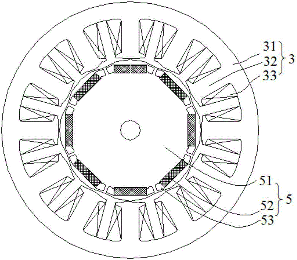
[0030] figure 1 It is a structural schematic diagram of a combination structure of a stator and a rotor provided by an embodiment of the present invention, see figure 1 , the permanent magnet motor includes a stator 3 and a rotor 5 .

[0031] Wherein, the stator 3 includes a stator core 31, the stator core 31 is provided with winding teeth 32 opposite to the rotor 5, and the winding teeth 32 are evenly distributed on the stator core 31, and the winding teeth 32 are wound with an armature Winding 33.

[0032] The rotor 5 includes a rotor core 51 and a plurality of magnetic steels 52 , and a plurality of installation grooves 53 are evenly spaced on the circumference of the rotor iron core 51 , and each installation groove 53 is respect...


PUM


Abstract

The invention discloses a stator and rotor combined structure and belongs to the motor field. The stator and rotor combined structure includes a stator and a rotor; the stator includes a stator core; the stator core is provided with wire winding teeth opposite to the rotor; the wire winding teeth are uniformly distributed on the stator core; the wire winding teeth are wound with an armature winding; the rotor includes a rotor core and a plurality of magnets; a plurality of mounting grooves are uniformly distributed at intervals along the circumferential direction of the rotor core; one magnet is embedded in a corresponding mounting groove; the plurality of magnets include first magnets and second magnets, wherein the first magnets are adjacent to the second magnets; the axis of symmetry of the first magnet, which passes through the center of the rotor is a D axis; an axis of symmetry between the first magnet and the second magnet, which passes through the center of the rotor is a Q axis; the distance from points on the outer contour line of an end surface of the rotor to the side walls of the wire winding teeth is g; and in a sector scope from the Q axis to the D axis, g is decreased from the Q axis to the D axis.

Description

technical field [0001] The invention relates to the field of motors, in particular to a combined structure of a stator and a rotor. Background technique [0002] A permanent magnet motor mainly includes a rotor having a magnet pole portion made of magnet steel, and a stator including an iron core and an armature winding. [0003] According to the winding method of the armature winding, the permanent magnet motor is divided into two structures: fractional slot winding and integer slot winding. The permanent magnet motor with fractional slot winding greatly reduces the slot area occupied by the insulating support, so that the actual slot fullness of the armature winding can be increased, the resistance of the winding can be reduced, and the efficiency of the motor can be improved. [0004] However, for permanent magnet motors with fractional slot windings, the armature reaction contains a large number of high-order harmonics, which will increase the iron loss of the motor; an...

Claims


Application Information

Patent Timeline
Patent Type & Authority Applications(China)
IPC IPC(8): H02K21/14H02K29/03H02K1/27
CPCH02K1/146H02K1/2766H02K29/03H02K2201/03H02K2213/03
Inventor 杨奎林李更祥王磊
Owner BERGSTROM CHINA GRP
Why Eureka
Try Eureka