Synchronous rectification control circuit and method based on secondary-side current sampling

A technology of synchronous rectification and secondary current, applied in the direction of irreversible AC power input conversion to DC power output, etc., can solve the problems of no rectification dead zone adjustment capability, complex circuit design, poor availability, etc., to achieve low power consumption, Simple circuit and good linearity

Active Publication Date: 2015-12-23
BEIJING SATELLITE MFG FACTORY
View PDF5 Cites 6 Cited by
  • Summary
  • Abstract
  • Description
  • Claims
  • Application Information

AI Technical Summary

Problems solved by technology

This method requires accurate sampling of the voltage at the DS terminal, and requires the use of a high-speed comparator to achieve efficient control. The circuit design is complex, there are many components, and the cost is high.
[0005] In the existing technology, synchronous rectification control is also implemented based on secondary side current acquisition. For example, the patent publication number applied by Huawei Technologies Co., Ltd. is CN103475195A, and the name is "A Synchronous Rectification Control Circuit and Synchronous Rectification Control Method". This patent uses As the core logic interpretation device, the current mirror comparator has poor availability, complex circuits, high power consumption, and no ability to adjust the rectification dead zone in the field of aerospace applications.

Method used


Image

  • Synchronous rectification control circuit and method based on secondary-side current sampling
  • Synchronous rectification control circuit and method based on secondary-side current sampling
  • Synchronous rectification control circuit and method based on secondary-side current sampling

Examples


Embodiment Construction
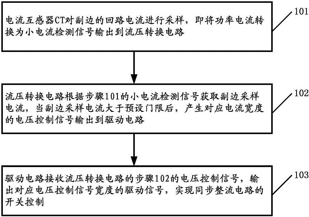
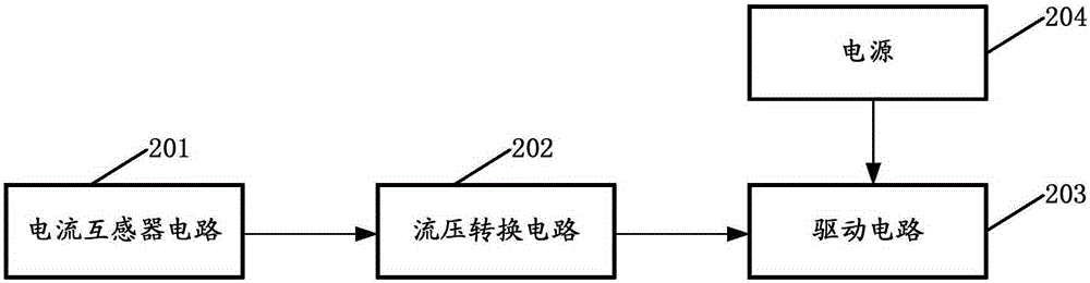
[0043] The basic idea of ​​the present invention is to provide a synchronous rectification control circuit based on secondary side current sampling, including: a current transformer CT, connected in series to the secondary side, sampling the loop current of the secondary side, converting the power current into a small current detection signal; the current-voltage conversion circuit, whose input terminal is connected to the current transformer CT, the current-voltage conversion circuit obtains the sampling current of the secondary side according to the current detection signal, and outputs a voltage control signal corresponding to the current width when the current is greater than the preset threshold; the drive circuit , receiving the voltage control signal of the current-voltage conversion circuit, outputting the driving signal corresponding to the width, and realizing the switching of the synchronous rectification circuit. According to the synchronous rectification circuit an...


PUM


Abstract

The invention relates to a synchronous rectification control circuit and method based on secondary-side current sampling, belonging to the overall technical field of aerospace. The circuit comprises a current transformer CT, a current-voltage conversion circuit and a driving circuit, wherein the current transformer CT is connected to a secondary side in series and is used for sampling the loop current of the secondary side and converting power current into a small-current detection signal; the input end of the current-voltage conversion circuit is connected with the current transformer CT, and the current-voltage conversion circuit is used for acquiring the sampling current of the secondary side according to the current detection signal and outputting a voltage control signal corresponding to current width when the current is greater than a preset threshold; and the driving circuit is used for receiving the voltage control signal from the current-voltage conversion circuit and outputting a driving signal corresponding to the width so as to achieve switch-on and switch-off of the synchronous rectification control circuit. According to the synchronous rectification control circuit and the synchronous rectification control method, high-speed and reliable control on a synchronous rectification tube can be achieved, and the circuit and the method have the advantages of control simplicity and easiness in implementation.

Description

technical field [0001] The invention relates to a synchronous rectification control circuit and method based on secondary side current sampling, and belongs to the technical field of spacecraft synchronous rectification control circuits. Background technique [0002] The rapid development of spacecraft puts forward higher and higher requirements for its power distribution system, especially with the gradual strengthening of satellite load complexity and functions, higher requirements are put forward for the miniaturization and high efficiency of on-board DC-DC converters. The miniaturization and high efficiency of DC-DC converters require that the operating frequency be increased while reducing heat consumption. Therefore, more and more synchronous rectification technologies are introduced in the design of on-board DC-DC converters. However, the control of the synchronous rectification circuit is relatively complicated, and it is easy to bring reliability risks while obtaini...

Claims


Application Information

Patent Timeline
Patent Type & Authority Applications(China)
IPC IPC(8): H02M7/06
Inventor 刘密谢鹏飞纪志坡
Owner BEIJING SATELLITE MFG FACTORY
Why Eureka
Try Eureka